I’m sharing an inverter project today that I think is the world’s most straightforward bi-stable inverter circuit.
Describe the idea of inverters that are bi-stable.
An inverter that uses a bi-directional flow of power to stabilize the output voltage and frequency is known as a bi-stable inverter. For applications requiring a steady output voltage and frequency, such as charging small electronic items like laptops, phones, and AC lamps, this kind of inverter is crucial.
the advantages of bi-stable inverter technology.
The application of bi-stable inverters has numerous advantages, such as:
They can lessen the wastage of energy.
They have the potential to reduce your electricity costs.
It can be utilized in the house in the event of a power loss.
They can assist you in lessening your reliance on the grid.
They can assist you in making less noise.
Anyone with little to no experience with electronics may complete this project because the circuitry is so basic.
Talk about the various kinds of bi-stable inverters.
The bi-stable inverter transistor: It employs two transistors, one of which turns on when the other turns off, and vice versa; this mechanism is known as a flip-flop.
IC Inverter with bi-stability: integrated circuit I’ll write a piece on integrated circuits that produce bi-stable inverters soon. Some examples of these circuits are IR2153 and CD4047.
A TRANSISTOR INVERTER IS THIS TYPE OF BI-STABLE INVERTER.
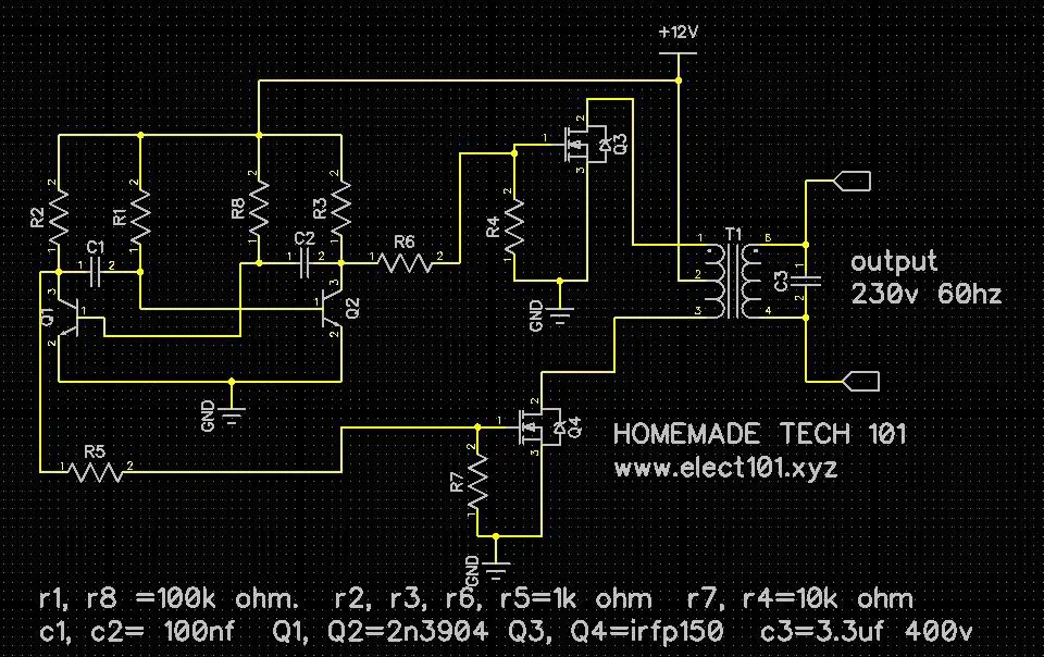
Its oscillator circuit, the Bi-Stable Multivibrator, consists of two transistors, eight resistors, three capacitors, two Mosfets, and a 12-volt transformer with a center cap (12v-0v-12v) Below is a list of the component values that were used.
components consist of:
4 pieces of 1k resistors
Two pieces of 10k resistor
Two pieces of 100k resistor
4.100nf (104j) two-piece capacitor
1 piece 3.3 uf (335 j) capacitor
Two BC3904 transistors
Two pieces of IRFP150 MOSFET
12v*2 transformer, also known as 12v-0v-12v transformer
Below is a picture of the schematic for the inverter project.

HERE IS THE VIDEO IN WHICH I TEST THIS PROJECT, AN INVERTER CIRCUIT.
>> To get the schematic, click this link <<
We appreciate you viewing our video and reading our article.
Please tell your friends about this post.
and remember to follow our YouTube channel.
o