Power outages can cause significant disruptions. An inverter is a crucial device that guarantees a reliable power source in times of emergencies or when portable power is required. In this tutorial, we’ll walk you through the process of constructing a basic and affordable DC-to-AC inverter using the versatile 555 timer IC and easily accessible components.
What exactly is an inverter?
An inverter is a power electronic device that transforms direct current (DC) from sources such as batteries into alternating current (AC), which is the standard for household appliances. This project is ideal for providing power to small devices in case of power outages or for outdoor activities.
Advantages of a DIY 555 Inverter:
Affordable: Constructing your own inverter is much more budget-friendly compared to purchasing a pre-made one.
Informative: An excellent opportunity to gain knowledge about electronics and power conversion principles.
Flexible: The output power can be adjusted to meet your individual requirements.
Materials Needed
The IC NE555 Timer: (1)
Here are two types of transistors you might find useful: – TIP41A (NPN) – TIP42A (PNP)
Transformer: Choose the primary voltage that suits your region.
A 12-0-12V center-tapped transformer is used to provide a 120V output.
A center-tapped transformer is used to provide a 240V output with a 24-0-24V input.
Resistors available: 10KΩ (1) 100KΩ (1) 100Ω (1)
Resistor with adjustable resistance: 50KΩ (1)
Capacitors: 0.1µF (1) 0.01µF (1) 2200µF (1)
Connecting wires
Battery: 12V (or adjust according to the primary voltage rating of the transformer)
It is recommended to use a breadboard.
Heat sinks for transistors
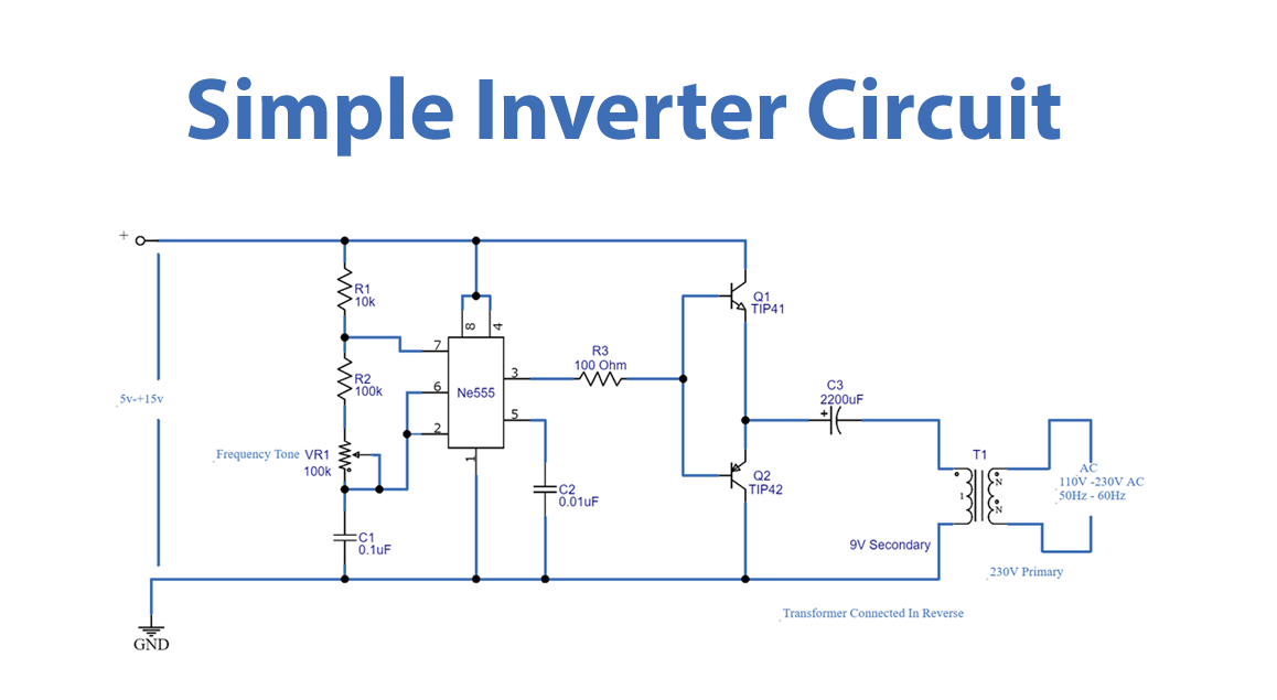
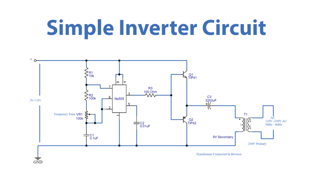
Schematic
circuit diagram of the 555 timer inverter.
How the Process Functions
The 555 timer IC is configured as an astable multivibrator, serving as the core component of the circuit. This creates a steady square wave pulse that regulates the switching of the transistors.
Transistor Switching: The TIP41A and TIP42A transistors serve as switches, connecting the transformer’s center tap to the positive and negative terminals of the battery in an alternating fashion.
Through the process of voltage transformation, the transformer is utilized in a reverse manner, resulting in an increase in the input voltage and ultimately generating a higher voltage AC output.
The output frequency is determined by the values of the resistors and capacitors connected to the 555 IC. By adjusting the variable resistor, you have the ability to finely tune the frequency to your desired level, usually set at either 50Hz or 60Hz.
Mathematical computations
The output voltage is determined by multiplying the battery voltage by the turn ratio of the transformer.
Frequency can be calculated using the formula f = 1.44 / ((R1 + 2*R2) * C1).
Building and Experimentation:
Let’s put together the circuit: Thoroughly adhere to the circuit diagram, being mindful of the polarity of the components.
Ensure that heat sinks are properly attached to the transistors to avoid any potential overheating issues.
Ensure Battery Connection: It is important to thoroughly inspect your connections prior to activating the power.
Test Output: Utilise a multimeter to accurately measure the AC voltage and frequency at the secondary of the transformer.
Key Points:
The output waveform of this inverter is a modified square wave, rather than a pure sine wave. It might not be the best choice for delicate electronic devices.
Power Limitations: This design is specifically tailored for low-power applications. Ensure that it is not overloaded.
Keys: Inverter project, timer circuit, converting DC to AC, electronics project, power backup
If you have any other requests or changes for this blog post, please feel free to let me know!