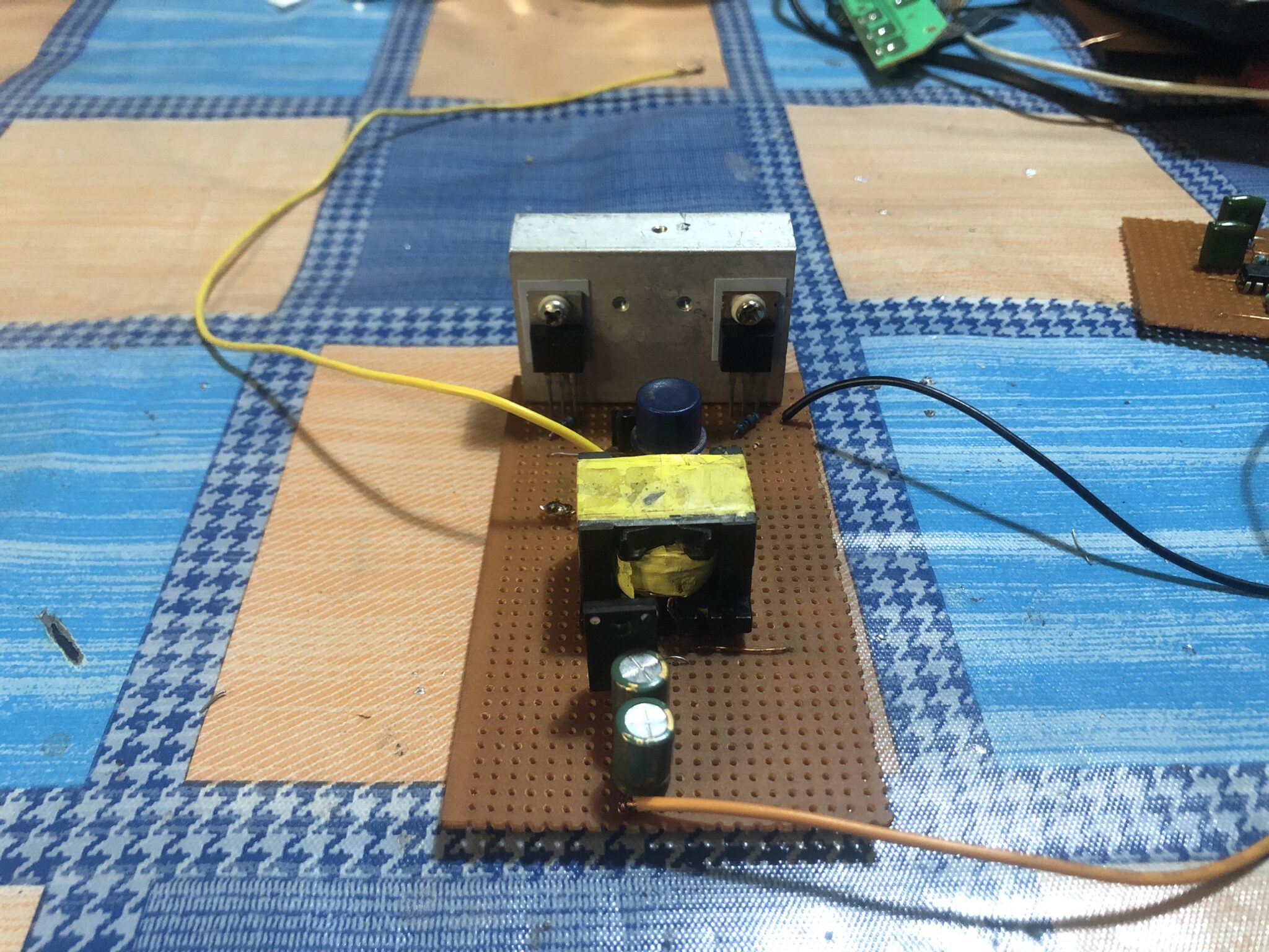
This project is a basic SMPS 12v to 19v boost converter circuit or project for charging laptops and other devices that require a higher voltage than 12v.
Switched Mode Power Supplies (SMPS)
Switched-Mode Power Supplies, also known as SMPS, play a crucial role in the field of electronics by efficiently delivering controlled power. In this blog post, we delve into the intricacies of creating a 12V to 19V boost converter using the SG3525 PWM controller and IRFZ44 MOSFETs. This design is centered around the SG3525, a PWM controller. It offers precise control to optimize power source performance.
SG3525 functions as a PWM controller.
Our boost converter relies on the functionality of the SG3525 PWM processor. This versatile IC enables the generation of precise PWM signals by utilizing an external feedback loop, allowing for highly accurate control of the output voltage. Due to its versatility, it is frequently selected for various power source configurations, particularly when increasing the voltage from 12V to 19V.
MOSFETs in Switching Applications
In order to achieve efficient power conversion, a push-pull arrangement is implemented using two IRFZ44 MOSFETs as the switching elements. These MOSFETs excel at handling high-frequency switching, resulting in reduced power loss and improved overall efficiency.
Managing the Schedule and Gate Access
To ensure optimal switching, it is crucial that the gate control of the IRFZ44 MOSFETs functions effectively. Using 6.8kΩ gate-to-source resistors simplifies the management of the switching between on and off states. These 47Ω resistors that connect the PWM input of the SG3525 to the MOSFET gates play a crucial role in fine-tuning the switching characteristics, resulting in improved performance of the converter.
Altering the pulse and rectification
The SG3525 PWM signal is isolated from the power circuit using a push-pull pulse transformer. This enhances safety and reliability. Following the transformer, a Schottky diode and a 25V 470µF capacitor collaborate to effectively refine and rectify the pulsed output. This produces a reliable 19V DC output that can safely power electronic devices.
Understanding the feedback loop and voltage control
Maintaining a consistent output voltage is crucial. A feedback loop is established in our 12V to 19V boost converter by connecting a 10kΩ resistor to the output and a 10kΩ potentiometer. Thanks to this loop, the SG3525 has the ability to dynamically change the PWM duty cycle based on the difference between the desired output voltage and the real output voltage.
With the 10kΩ potentiometer, you have the ability to adjust the input to the SG3525, allowing for precise control over the output voltage. When the output voltage deviates from the set value, the PWM signal is adjusted by the feedback loop. The 19V output remains stable and accurate.
Component Utilized
Resistors
The values of resistors R1, R2, and R4 are all 47 ohms.
The resistance value is 220 kilohms.
The values of R7 and R8 are 6.8Kohms.
The values of R5 and R9 are 10Kohms.
The value of resistor R6 is 10 kilohms.
Mosfets
What are the values of Q1 and Q2? They are IRFZ44.
Integrated circuits (ICs)
U1 is SG3525.
Capacitors
The total energy of C1, C2, and C7 is 104J.
The value of C3 is 102J.
The values of C4 are 25V and 470UF.
Transformer
For the pulse transformer, the primary winding has a center tap with 4*2 turns, while the secondary winding has 6 turns.
Control
A power switch is used to control the flow of electricity in a circuit, allowing you to easily turn it on and off.
Watch the video here
In conclusion
The SG3525 12V to 19V boost converter with IRFZ44 MOSFETs is a dependable and efficient method for providing power. The SG3525 PWM controller, IRFZ44 MOSFETs, pulse transformer, and feedback loop were selected for their ability to deliver exceptional performance, reliability, and stability.
This boost converter exemplifies the seamless integration of advanced PWM control, high-frequency switching, and effective feedback systems. The seamless integration of these components ensures optimal power conversion for a wide range of electronic devices.