Introduction
Musical instruments are just one example of how electronic devices have become an integral element of modern life in this digital era. For those interested in music and electronics, constructing a simple electronic piano or organ using an astable circuit is a captivating hobby. One type of oscillator that produces a symmetrical and continuous signal is an astable circuit. We may build a basic yet entertaining musical instrument by using the specifications of this circuit.
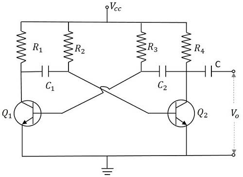
Simple topology diagram for Astable
Building your own electronic piano or organ using an astable circuit is a fun and instructive project that fans of all ages can do, and we’ll show you how to do it in this post.
The Astable Circuit: A Comprehensive Overview It is critical to understand the basics of the astable circuit before beginning to construct the electronic organ or piano. Without a steady nation, an astable circuit—a network of digital additives—generates a continuous rectangular wave output.
Ordinarily, it consists of transistors, capacitors, and resistors. An astable circuit relies on the timing capacitor, whose controlled charging and discharging determines the square wave output frequency.
Changing the values of capacitors and resistors allows us to manipulate the electronic instrument’s output in terms of both frequency and tone.
Putting Everything Together Here are some things you would need to assemble a simple electronic organ or piano:
1. Resistors: Choose the right resistors based on the output frequency you like.
Second, select capacitors whose frequency range and tone you want.
3. Transistors: Astable circuits often make use of NPN and PNP transistors.
Fourthly, the speaker: choose a speaker that can make the desired sound.
5. Power Source: Incorporate a voltage source into your circuit that falls within the 9v to 12v range.
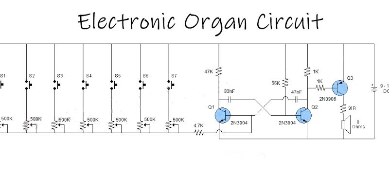
The electrical organ system

Assembling the Circuit Here are the steps to build the virtual piano or organ:
1. Begin by constructing the astable oscillator circuit by connecting the capacitors and resistors. Before purchasing any components, be careful to read the associated datasheets and reference documents.
Step 2: Ensure proper polarity and orientation when connecting the transistors to the oscillator circuit.
Third, connect the speaker to the circuit’s output pins. In order to make the electrical alarms audible, the speaker will transform them. Turn on the power source to bring a constant voltage to the circuit.
Part four:
The Keyboard Has Been You should incorporate a keyboard interface into your digital piano or organ circuit now that it is finished. A simple matrix keyboard with a few switches arranged in columns and rows is at your disposal.
There is a corresponding observe or tone for each switch.
Join the switch rows to the astable circuit’s output pins and the switch columns to the ground. By connecting two rows and columns, each key press causes the associated sound to be played through the speaker.
Trying New Things and Making Enhancements Now that you have a fully functional electronic piano or organ, you may start exploring different possibilities.
Playing around with the values of the resistors and capacitors allows you to fine-tune the frequency and tone. You might also think about including volume controls, save options, or perhaps a MIDI interface to make the circuit even more versatile.
In summary
Constructing an astable circuit-based electronic piano or organ is an interesting project that brings together the fields of electronics and track. Enthusiasts can build their own instrument while learning the fundamentals of oscillator circuits. Learning about electronics, circuitry, and sound creation through this do-it-yourself project is a fantastic idea.
Comments