PIC12F683 Inverter Circuit with Complete Project Files – Version 1
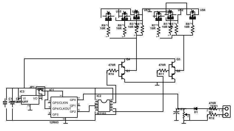
Welcome to an exciting project: the PIC12F683 Pure Sine Wave Inverter. This article provides everything you need to build your own efficient, cost-effective pure sine wave inverter. It includes detailed schematics, HEX code, project files, and even PCB designs for those interested in creating their own printed circuit boards (PCBs).
Introduction to the PIC12F683 Pure Sine Wave Inverter
This project focuses on creating a clean and stable 50 Hz sine wave output using the PIC12F683 microcontroller. The design is highly efficient and minimalistic, requiring only two integrated circuits (ICs), making it accessible for both beginners and experienced electronics enthusiasts.
The project is perfect for students looking for a simple yet impactful electronics project, particularly for final-year submissions. It combines cost-effectiveness, simplicity, and the satisfaction of building a functional and practical inverter circuit.
Why Choose the PIC12F683 Pure Sine Wave Inverter?
1. Simplicity and Flexibility
The circuit design is straightforward, involving just two 8-pin ICs, a few transistors, and MOSFETs. This makes it easy to assemble and troubleshoot, even for individuals with limited experience in electronics.
2. Ideal for Electronics Students
This inverter is an excellent choice for students or hobbyists who:
- Need a reliable, budget-friendly project.
- Want a practical circuit with real-world applications.
- Seek an easy-to-understand design that facilitates learning.
3. Cost-Effective and Efficient
- The design minimizes component requirements, reducing costs without compromising functionality.
- By using readily available components, the project remains economical and accessible for anyone.
4. Open-Source and Customizable
All project files, including the schematic, HEX code, and PCB layout, are open-source. This allows users to modify and adapt the design to suit their specific needs.
Project Components and Resources
To build the PIC12F683 sine wave inverter, you’ll need the following:
Core Components
- PIC12F683 Microcontroller: Acts as the brain of the inverter, generating the sine wave.
- IR2103 MOSFET Driver: Ensures proper switching of the MOSFETs to generate high and low sides of the sine wave.
- MOSFETs: Switch high-voltage DC to produce a sine wave output.
- Passive components (resistors, capacitors, etc.) for the supporting circuitry.
Provided Resources
- Schematic Diagram: A complete guide to assembling the circuit.
- HEX Code: Precompiled firmware for the PIC12F683 microcontroller.
- PCB Layout: For those who wish to create a professional-looking printed circuit board.
- Demonstration Video: A visual guide to understanding the functionality of the inverter.

Challenges and Solutions
Issue with MOSFET Driver (IR2103):
The IR2103 MOSFET driver can encounter issues when connected to a 12V supply. The high-side output delivers 12V instead of the expected 6V. This occurs due to a 5-second delay in the microcontroller’s HEX file, causing the high side to turn on while the low side remains off. This can directly trigger the MOSFETs with voltage, potentially damaging the circuit.
Solution – Adding a Delay Timer Circuit:
To resolve this, a 5-second delay timer circuit is added. The timer output is connected to the VCC pins (1 and 8) of the IR2103, ensuring proper synchronization between the microcontroller and the MOSFET driver. This prevents premature activation of the MOSFETs and protects the circuit.
Step-by-Step Guide to Building the Inverter
1. Assemble the Circuit
Using the provided schematic, assemble the circuit on a breadboard or PCB. Ensure all connections are secure and components are placed correctly.
2. Program the PIC12F683
Upload the HEX file to the PIC12F683 microcontroller using a suitable programmer. Ensure the microcontroller is properly programmed and tested before integrating it into the circuit.

3. Add the Delay Timer Circuit
Integrate the 5-second delay timer circuit to address the MOSFET driver issue. Adjust the preset VR to achieve a delay of at least 5 seconds.
4. Test the Inverter
Before connecting a load, test the circuit to verify that it generates a clean sine wave at 50 Hz. Use an oscilloscope to confirm the waveform and ensure stable operation.
5. Integrate and Use
Once testing is complete, the inverter is ready for use. Connect a suitable load and observe the performance.
Advantages of This Inverter Compared to Others
- Low Cost: Ideal for students and hobbyists on a budget.
- Simplicity: minimal component count, with just two ICs and a few transistors.
- Customizable: Open-source project files allow users to modify and adapt the design.
- Educational Value: Perfect for learning and understanding the basics of sine wave generation and inverter design.
Downloads and Resources
- Download Complete Project Files Here
- Watch the demonstration video below to see the inverter in action.
Conclusion
The PIC12F683 Pure Sine Wave Inverter is a simple, efficient, and cost-effective solution for anyone interested in learning or building an inverter circuit. Whether you’re a student, hobbyist, or electronics enthusiast, this project offers a practical way to explore inverter design and sine wave generation.
Stay tuned for more updates and improvements by following this blog. Don’t forget to share your feedback and experiences with this project!
