Top 20 Terms and Devices in Electrical and Electronics: A Beginner’s Guide

top-20-electronics

For anyone new to the world of electrical and electronics, it can often feel like there is an overwhelming amount of terminology and components to understand. From basic circuits to advanced semiconductor devices, getting a solid foundation is essential for progressing in the field. This guide will take you through the top 20 key terms and devices, providing a simple and clear explanation of each one to help you get started.

1. Open Circuit

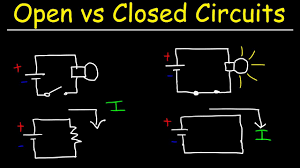
An open circuit occurs when there is a break in the path of an electrical circuit, preventing current from flowing. It is essentially an incomplete circuit, meaning no electricity can travel from the power source to the load (like a light bulb or motor).

2. Short Circuit

A short circuit happens when an unintended low-resistance path allows excessive current to flow. This usually occurs when two wires touch, bypassing the load and causing a potentially dangerous increase in current. Short circuits can cause overheating, damage to components, or even fires.
open-and-close-circuit

3. Parallel Circuit

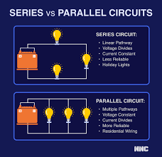
In a parallel circuit, multiple components are connected side by side, each having its own path to the power source. This means if one component fails, the others can still function. Parallel circuits are commonly used in household wiring systems where different appliances operate independently.

4. Series Circuit

In a series circuit, components are connected one after the other in a single path. The current flows through each component in turn. If one component fails, the entire circuit is broken. A good example is older string lights for holiday decorations—if one bulb goes out, they all do.
series-and-parallel

5. Bridge Rectifier

A bridge rectifier is a type of circuit that converts alternating current (AC) into direct current (DC). It is made up of four diodes arranged in a “bridge” configuration. This is commonly used in power supply circuits to provide DC voltage from an AC source.
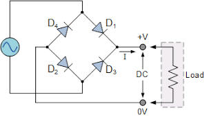
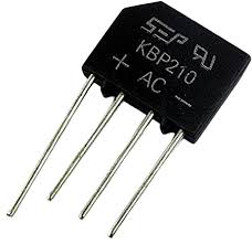
rectifier1
rectifier

6. LED (Light Emitting Diode)

LEDs are semiconductor devices that emit light when an electrical current flows through them. They are highly energy-efficient and are used in everything from indicator lights to large display screens. LEDs are favored for their low power consumption and long lifespan.

7. Switch

A switch is a simple device used to control the flow of electrical current in a circuit. When the switch is “on,” it closes the circuit, allowing current to flow. When it is “off,” it opens the circuit, stopping the current. Switches come in various forms such as toggle switches, push-button switches, and slide switches.

8. Battery

A battery is a device that stores chemical energy and converts it into electrical energy to power circuits. Batteries have two terminals: positive and negative. They come in many forms, such as disposable alkaline batteries and rechargeable lithium-ion batteries used in smartphones and laptops.

9. MOSFET (Metal-Oxide-Semiconductor Field-Effect Transistor)

A MOSFET is a type of transistor used for switching and amplifying signals in electronic devices. It is widely used in power electronics due to its high efficiency and fast switching speed. MOSFETs are commonly found in switching power supplies and motor control circuits.
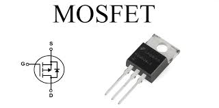
mosfet

10. BJT (Bipolar Junction Transistor)

A BJT is another type of transistor that controls current flow. It has three layers and two junctions, making it slightly different from MOSFETs. BJTs are commonly used for amplification and switching. The two main types of BJTs are NPN and PNP, named after the arrangement of their semiconductor layers.
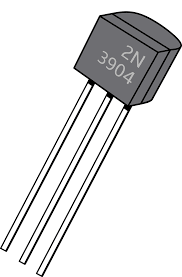
bjt

11. Resistor

Resistors are passive components that limit the flow of electric current in a circuit. They are used to control voltages and currents to protect other components. Resistors are rated by their resistance value, measured in ohms (Ω), and their power rating, measured in watts (W).

resistor

12. Capacitor

A capacitor is a device that stores and releases electrical energy. It is made of two conductive plates separated by an insulating material. Capacitors are used in many applications, such as filtering signals, stabilizing power supplies, and for timing circuits. The unit of capacitance is the farad (F).
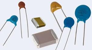
capacitor

13. Transformer

A transformer is a device that transfers electrical energy between two or more circuits through electromagnetic induction. It is primarily used to step up (increase) or step down (decrease) voltage levels. Transformers are essential in power transmission systems for distributing electricity over long distances.
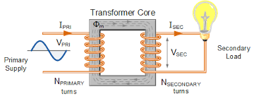
transformer

14. Inductor

An inductor is a passive component that stores energy in a magnetic field when current flows through it. Inductors are commonly used in filters, transformers, and to manage high-frequency signals in electronic circuits. Its unit is the henry (H).
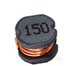
inductor

15. SCR (Silicon Controlled Rectifier)

An SCR is a type of semiconductor device used as a switch to control high voltages and currents. It only conducts when a gate signal is applied, making it useful for controlling power in devices like motor drives, heaters, and lighting systems.
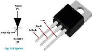
scr

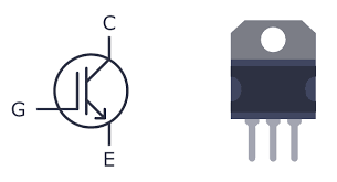
16. IGBT (Insulated Gate Bipolar Transistor)

IGBTs combine the best features of BJTs and MOSFETs. They are used in high-power applications like electric cars and industrial equipment, where high efficiency and fast switching are required.
igbt

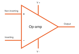
17. Operational Amplifier (Op-Amp)

An op-amp is a high-gain voltage amplifier with differential input and single-ended output. It is used in many applications, including signal conditioning, filtering, and analog computing. A popular configuration of the op-amp is the comparator, where it compares two voltages and outputs a high or low signal depending on the comparison.
opamp

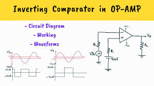
18. Comparator

A comparator is a specialized op-amp that compares two input voltages and outputs a digital signal based on which input is higher. Comparators are commonly used in zero-crossing detectors, oscillators, and voltage-level detection circuits.
comparator

19. Logic Gates

Logic gates are the building blocks of digital circuits. They perform basic logical functions (AND, OR, NOT, NAND, NOR, XOR, XNOR) by outputting a specific result based on binary input signals (0s and 1s). Logic gates are fundamental in processors, memory devices, and other digital systems.

logic

20. Diodes and Their Types

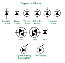
A diode is a semiconductor device that allows current to flow in one direction only. Diodes are used for rectification, voltage regulation, and protection. There are several types of diodes:
diodes
  • Standard Diode: Used in rectification circuits to convert AC to DC.
  • Zener Diode: Allows current to flow in reverse when a certain voltage is reached, often used for voltage regulation.
  • Schottky Diode: Has low forward voltage drop and fast switching, used in high-speed circuits.
  • Light Emitting Diode (LED): Emits light when forward biased.
  • Photodiode: Converts light into current, commonly used in sensors.

Conclusion

Understanding these essential terms and devices is the first step toward mastering electrical and electronics concepts. Whether you’re working with simple circuits or complex electronic systems, having a strong grasp of these components will help you design, troubleshoot, and innovate. For beginners, focusing on the practical applications of each device can also provide insight into how they fit together in larger systems.

1/10 Scale Radio-Controlled Electric-Powered 4WD Fazer MK2 FZ02 Review

Introduction

Get ready to take your RC racing experience to the next level with the 1/10 scale radio-controlled electric-powered 4WD Fazer MK2 FZ02! This high-performance RC car is designed for on-road and drift racing enthusiasts, delivering exceptional speed, agility, and control. In this review, we’ll dive into the key features, specifications, performance, and upgrade options of this impressive model.

Key Features

The Fazer MK2 FZ02 boasts an array of impressive features that make it a top contender in the RC racing world:

  • Scale: 1/10
  • Power: Electric
  • Drive: 4-Wheel Drive (4WD)
  • Chassis: Fazer MK2
  • Model: FZ02

Specifications

Here are the detailed specifications of the Fazer MK2 FZ02:

  • Length: approximately 17.3 inches (440mm)
  • Width: approximately 7.5 inches (190mm)
  • Height: approximately 5.1 inches (130mm)
  • Wheelbase: approximately 10.2 inches (260mm)
  • Weight: around 3.5 pounds (1.6 kg)
  • Motor: Brushless electric motor
  • Transmission: 4WD with shaft drive
  • Suspension: Independent suspension with coil springs
  • Wheels: 1.9 inches (48mm) diameter, 1.2 inches (30mm) width
  • Tire type: On-road or drift tires (depending on configuration)

Performance

The Fazer MK2 FZ02 delivers exceptional performance on the track:

  • Top speed: up to 30-40 mph (48-64 km/h), depending on battery and gearing
  • Acceleration: excellent acceleration due to 4WD and brushless motor
  • Handling: stable and responsive, suitable for on-road and drift racing

Upgrades and Customization

Take your Fazer MK2 FZ02 to the next level with a wide range of upgrade and customization options:

  • Bodies and wings
  • Motor upgrades
  • ESC (Electronic Speed Controller) upgrades
  • Suspension upgrades
  • Wheel and tire upgrades

Where to Buy

Get your hands on the Fazer MK2 FZ02 at online RC hobby stores, such as:

  • Amazon
  • HobbyTown
  • Tower Hobbies
  • RCMart
  • Local hobby shops

Price Range

The price range for the Fazer MK2 FZ02 varies depending on the kit or RTR (Ready-to-Run) version, and any additional upgrades or accessories:

  • Kit: around $150-$250
  • RTR: around $250-$400
  • Upgraded versions: $400-$600 or more

Conclusion

The 1/10 scale radio-controlled electric-powered 4WD Fazer MK2 FZ02 is an exceptional RC car that delivers high-performance, agility, and control. Whether you’re an experienced RC enthusiast or just starting out, this model is sure to provide hours of thrilling racing action. With its impressive features, specifications, and upgrade options, the Fazer MK2 FZ02 is a must-have for any RC racing fan.

Rating: 4.5/5 stars

Recommendation: If you’re looking for a high-performance RC car for on-road and drift racing, the Fazer MK2 FZ02 is an excellent choice.

Have you experienced the thrill of the Fazer MK2 FZ02? Share your thoughts and reviews in the comments below!

Understanding ECG Signals with AD8232 Sensor Module

AD8232 Sensor

In today’s post, we’ll delve into the electrical activity of the heart, focusing on how it contracts and relaxes, generating signals known as electrocardiograms (ECGs). By interpreting ECG signals, we can understand heart function and identify potential health issues. We’ll explore how to use the AD8232 sensor module to measure heart activity and visualize the ECG graph.

What is an ECG?

An electrocardiogram (ECG or EKG) is a recording of the electrical signals produced by the heart. It is used to determine heart rate, rhythm, and other critical information about heart activity. The ECG graph consists of various components that correspond to specific cardiac events:

  • P wave: Represents atrial contraction.
  • QRS complex: Indicates ventricular depolarization and contraction. It includes:
  • Q wave: Initial downward deflection.
  • R wave: Large upward deflection.
  • S wave: Downward deflection following the R wave.
  • T wave: Represents ventricular repolarization.

Using the AD8232 Sensor Module

The AD8232 sensor module is designed to measure heart activity. Here’s a step-by-step guide on how to use it:

Components and Setup

  1. AD8232 Sensor Module: Purchased from Amazon, this module comes with a set of electrodes and a 3.5mm connecting rod.
  2. Pins on AD8232: The module has nine pins, but we will use the following:
  • GND: Ground
  • 3.3V: Power supply
  • OUTPUT: Signal output
  • LO-: Leads-off detection negative
  • LO+: Leads-off detection positive
  1. Electrodes: The module includes three electrodes that attach to specific body parts (e.g., arms, chest) using adhesive gel.

Wiring the Module

  1. Connect GND to the ground pin on your microcontroller.
  2. Connect 3.3V to the 3.3V power supply pin.
  3. Connect OUTPUT to an analog input pin (e.g., A0).
  4. Connect LO- to a digital pin (e.g., D11).
  5. Connect LO+ to another digital pin (e.g., D10).

Placing the Electrodes

The electrodes should be placed as follows:

  • Red electrode: Right side of the chest.
  • Green electrode: Left side of the body, below the heart.
  • Yellow electrode: On the lower torso, around the liver area.

Alternatively, you can place the electrodes on your arms and legs.

Uploading the Code

Here’s a simple code snippet for reading the ECG signal using an Arduino:

void setup() {
  Serial.begin(9600);
  pinMode(10, INPUT);
  pinMode(11, INPUT);
}

void loop() {
  int ecgValue = analogRead(A0);
  Serial.println(ecgValue);
  delay(1);
}
  1. Upload the code to your Arduino.
  2. Open the serial plotter in the Arduino IDE to visualize the ECG graph.

Visualizing the ECG

You can view the ECG graph on the Arduino serial plotter or use an oscilloscope for a more detailed analysis. Additionally, the data can be processed using software like Processing IDE for better visualization. A link to the Processing code is provided in the description for those interested.

Conclusion

Using the AD8232 sensor module, you can easily measure and visualize ECG signals, helping you understand heart activity and detect potential health issues. By following this guide, you can set up the sensor, connect it to an Arduino, and start analyzing ECG data.

For more detailed information and the Processing code, check the links provided. Happy experimenting with your heart health monitoring project!

Arduino Serial Communication: Mastering Serial Monitor and Plotter

Arduino, a popular microcontroller platform, offers an excellent toolset for communicating between your Arduino board and your computer. The Arduino Serial Monitor and Serial Plotter provide real-time data interaction, essential for debugging and monitoring. This post will guide you through the intricacies of serial communication with Arduino, focusing on key functions like Serial.begin(), Serial.print(), Serial.read(), and more.

Table of Contents

  1. Understanding Arduino Serial Communication
  • What is Serial Communication?
  • Setting up the Arduino Serial Port
  1. Getting Started with Arduino Serial Monitor
  • How to Open Serial Monitor
  • Printing to Serial Monitor with Serial.print()
  • Example: Hello World
  1. Reading Data from the Serial Port
  • Using Serial.read()
  • Example: Echo Input
  1. Advanced Serial Communication Techniques
  • Using Serial.write()
  • Example: Sending Binary Data
  1. Visualizing Data with Arduino Serial Plotter
  • How to Use Serial Plotter
  • Plotting Real-time Data
  1. Tips for Efficient Serial Communication
  2. Conclusion

1. Understanding Arduino Serial Communication

What is Serial Communication?

Serial communication is a process of sending data one bit at a time, sequentially, over a communication channel. In the context of Arduino, this is typically done using a USB connection between your Arduino board and computer.

Setting up the Arduino Serial Port

To begin serial communication, you must initialize the serial port using the Serial.begin() function. This function sets the data rate in bits per second (baud) for serial data transmission.

void setup() {
  Serial.begin(9600);  // Initialize serial communication at 9600 baud
}

2. Getting Started with Arduino Serial Monitor

The Arduino Serial Monitor is a built-in feature of the Arduino IDE that allows you to send and receive text data between your Arduino board and your computer.

How to Open Serial Monitor

To open the Serial Monitor, click on the magnifying glass icon in the top-right corner of the Arduino IDE or go to Tools > Serial Monitor.

Printing to Serial Monitor with Serial.print()

Use the Serial.print() and Serial.println() functions to send data to the Serial Monitor.

void setup() {
  Serial.begin(9600);
}

void loop() {
  Serial.println("Hello, World!");  // Print "Hello, World!" to the Serial Monitor
  delay(1000);  // Wait for 1 second
}

Example: Hello World

This simple example demonstrates how to print “Hello, World!” to the Serial Monitor every second.

3. Reading Data from the Serial Port

Using Serial.read()

The Serial.read() function reads incoming serial data. Here’s how you can use it:

void setup() {
  Serial.begin(9600);
}

void loop() {
  if (Serial.available() > 0) {
    char incomingByte = Serial.read();
    Serial.print("I received: ");
    Serial.println(incomingByte);
  }
}

Example: Echo Input

This example reads data from the serial port and echoes it back to the Serial Monitor.

4. Advanced Serial Communication Techniques

Using Serial.write()

The Serial.write() function sends binary data to the serial port. This is useful for sending non-text data.

void setup() {
  Serial.begin(9600);
}

void loop() {
  byte data = 0xA5;
  Serial.write(data);  // Send binary data
  delay(1000);
}

Example: Sending Binary Data

This example sends a single byte of binary data (0xA5) to the serial port every second.

5. Visualizing Data with Arduino Serial Plotter

The Arduino Serial Plotter is another tool in the Arduino IDE that graphs the values sent from the Arduino board.

How to Use Serial Plotter

To open the Serial Plotter, go to Tools > Serial Plotter in the Arduino IDE.

Plotting Real-time Data

To plot data, send numerical values followed by a newline character. The Serial Plotter will graph these values in real-time.

void setup() {
  Serial.begin(9600);
}

void loop() {
  int sensorValue = analogRead(A0);
  Serial.println(sensorValue);
  delay(100);
}

6. Tips for Efficient Serial Communication

  • Buffer Size: Ensure your serial buffer size is sufficient for your data.
  • Baud Rate: Choose an appropriate baud rate for your application to balance speed and reliability.
  • Error Handling: Implement error handling for robust communication.

7. Conclusion

Mastering Arduino’s serial communication tools, such as the Serial Monitor and Serial Plotter, can significantly enhance your projects’ debugging and data visualization capabilities. By understanding and utilizing functions like Serial.begin(), Serial.print(), Serial.read(), and Serial.write(), you can efficiently manage data exchange between your Arduino and computer.

Arduino with a 1602A LCD Display and I2C Interface

1602

Arduino enthusiasts often seek effective ways to display data, and integrating an LCD screen is a popular method. In this guide, we will delve into the use of a 1602A LCD display with an Arduino, focusing on the I2C interface for streamlined communication. This optimized guide covers setup, coding, and troubleshooting to ensure your project succeeds.

Introduction to the 1602A LCD Display

The 1602A LCD display is a versatile, user-friendly screen featuring 16 columns and 2 rows of alphanumeric characters. This display is perfect for projects requiring simple text output. Its I2C interface simplifies wiring and reduces pin usage on your Arduino, making it an efficient choice for many applications.

Why Use I2C with the 1602A LCD Display?

Benefits of I2C:

  • Fewer Pins Required: I2C uses only two pins (SDA and SCL) compared to the multiple pins needed for parallel communication.
  • Simplified Wiring: Reduces clutter and potential errors in connections.
  • Expandability: Allows multiple I2C devices on the same bus without additional pins.

Components Needed

  • Arduino (e.g., Arduino Uno, Nano)
  • 1602A LCD Display with I2C Interface
  • Jumper wires
  • Breadboard (optional)

Setting Up the 1602A LCD Display with Arduino

Step 1: Connecting the Hardware

  1. Connect the I2C module to the LCD:
  • Attach the I2C module to the back of the 1602A LCD display if not already attached.
  1. Wire the LCD to the Arduino:
  • GND: Connect to Arduino GND
  • VCC: Connect to Arduino 5V
  • SDA: Connect to Arduino A4 (for Arduino Uno/Nano)
  • SCL: Connect to Arduino A5 (for Arduino Uno/Nano)
1602

Step 2: Installing the Required Libraries

To use the 1602A LCD display with I2C, install the LiquidCrystal_I2C library:

  1. Open the Arduino IDE.
  2. Go to Sketch > Include Library > Manage Libraries.
  3. In the Library Manager, search for LiquidCrystal_I2C and install it.

Step 3: Writing the Code

Here’s a basic code example to get you started with displaying text on your 1602A LCD using I2C:

#include <Wire.h>
#include <LiquidCrystal_I2C.h>

// Initialize the library with the I2C address and LCD size
LiquidCrystal_I2C lcd(0x27, 16, 2); // 0x27 is a common I2C address for the module

void setup() {
  lcd.begin();         // Initialize the LCD
  lcd.backlight();     // Turn on the backlight

  // Print a message to the LCD
  lcd.setCursor(0, 0); // Set the cursor to column 0, row 0
  lcd.print("Hello, World!");
  lcd.setCursor(0, 1); // Set the cursor to column 0, row 1
  lcd.print("Arduino LCD");
}

void loop() {
  // Your code here (if any)
}

Step 4: Uploading and Testing

  1. Connect your Arduino to your computer using a USB cable.
  2. Select the correct board and port from the Tools menu in the Arduino IDE.
  3. Click the upload button to transfer the code to your Arduino.
  4. Once uploaded, you should see “Hello, World!” and “Arduino LCD” displayed on your 1602A LCD.

Troubleshooting Tips

  • No Display: Ensure all connections are secure and correct. Check if the I2C address matches your module’s address (common addresses are 0x27 and 0x3F).
  • Garbled Text: Adjust the contrast using the potentiometer on the I2C module.
  • Library Issues: Ensure you have the correct and updated version of the LiquidCrystal_I2C library.

Conclusion

Integrating a 1602A LCD display with your Arduino via I2C simplifies your project’s wiring and conserves precious GPIO pins. By following this guide, you should have a functioning setup displaying custom messages on your LCD screen. Experiment with different messages and incorporate this display into your broader projects for enhanced data visualization.

WiFi.h Arduino Library : WiFi Connectivity

Connecting your Arduino projects to the internet opens up a world of possibilities, from IoT applications to remote monitoring and control. One of the most powerful tools in your Arduino toolkit for enabling WiFi connectivity is the WiFi.h library. This guide will walk you through the fundamentals of using the WiFi.h library with your ESP32 or ESP8266 microcontroller, providing detailed examples and tips to optimize your code for reliable and efficient WiFi connections.

Introduction to the WiFi.h Library

The WiFi.h library is a robust and versatile library designed to simplify the process of connecting your Arduino-compatible ESP32 and ESP8266 microcontrollers to a WiFi network. With this library, you can easily connect to WiFi, manage network settings, and handle data communication over the network.

Getting Started with the WiFi.h Library

Before diving into the code, ensure you have the necessary hardware and software:

  1. Hardware: ESP32 or ESP8266 microcontroller, USB cable, and a computer for programming.
  2. Software: Arduino IDE installed on your computer. Ensure you have the appropriate board support package for your ESP32/ESP8266.

Step 1: Installing the ESP32/ESP8266 Board Support Package

To use the WiFi.h library, you need to install the board support package for your ESP32 or ESP8266:

  1. Open the Arduino IDE.
  2. Go to File > Preferences.
  3. In the “Additional Boards Manager URLs” field, add the following URLs:
  1. Click OK.
  2. Go to Tools > Board > Boards Manager.
  3. Search for “ESP32” or “ESP8266” and click Install.

Step 2: Including the WiFi.h Library

Start by including the WiFi.h library in your sketch:

#include <WiFi.h>

Step 3: Connecting to a WiFi Network

To connect your microcontroller to a WiFi network, you need to specify the network’s SSID and password:

const char* ssid = "your_SSID";
const char* password = "your_PASSWORD";

void setup() {
  Serial.begin(115200);

  WiFi.begin(ssid, password);

  while (WiFi.status() != WL_CONNECTED) {
    delay(1000);
    Serial.println("Connecting to WiFi...");
  }

  Serial.println("Connected to WiFi");
  Serial.print("IP Address: ");
  Serial.println(WiFi.localIP());
}

void loop() {
  // Your code here
}

Step 4: Checking Connection Status

Use WiFi.status() to check the connection status. This function returns WL_CONNECTED when the microcontroller is connected to a WiFi network:

if (WiFi.status() == WL_CONNECTED) {
  Serial.println("WiFi is connected");
} else {
  Serial.println("WiFi is not connected");
}

Step 5: Disconnecting from a WiFi Network

To disconnect from the current WiFi network, use WiFi.disconnect():

WiFi.disconnect();
Serial.println("Disconnected from WiFi");

Step 6: Retrieving Network Information

You can retrieve various information about the current network, such as the SSID, IP address, and MAC address:

String ssid = WiFi.SSID();
IPAddress ip = WiFi.localIP();
String mac = WiFi.macAddress();

Serial.print("SSID: ");
Serial.println(ssid);
Serial.print("IP Address: ");
Serial.println(ip);
Serial.print("MAC Address: ");
Serial.println(mac);

Step 7: Scanning for Available Networks

To scan for available WiFi networks, use WiFi.scanNetworks():

int n = WiFi.scanNetworks();
Serial.println("Scan done");
if (n == 0) {
  Serial.println("No networks found");
} else {
  Serial.print(n);
  Serial.println(" networks found");
  for (int i = 0; i < n; ++i) {
    Serial.print("SSID: ");
    Serial.println(WiFi.SSID(i));
    Serial.print("Signal strength (RSSI): ");
    Serial.println(WiFi.RSSI(i));
  }
}

Example Code: Putting It All Together

Here’s a complete example that demonstrates how to connect to a WiFi network, check the connection status, and retrieve network information:

#include <WiFi.h>

const char* ssid = "your_SSID";
const char* password = "your_PASSWORD";

void setup() {
  Serial.begin(115200);

  WiFi.begin(ssid, password);

  while (WiFi.status() != WL_CONNECTED) {
    delay(1000);
    Serial.println("Connecting to WiFi...");
  }

  Serial.println("Connected to WiFi");
  Serial.print("IP Address: ");
  Serial.println(WiFi.localIP());
}

void loop() {
  if (WiFi.status() == WL_CONNECTED) {
    Serial.println("WiFi is connected");
  } else {
    Serial.println("WiFi is not connected");
  }
  delay(5000);
}

Optimization Tips

To ensure reliable and efficient WiFi connectivity, consider the following tips:

  1. Use Static IP: If your application requires a stable IP address, consider using a static IP configuration.
  2. Optimize Power Consumption: Use deep sleep modes and other power-saving techniques to extend battery life in portable projects.
  3. Handle Connection Loss: Implement reconnection logic to handle scenarios where the WiFi connection drops unexpectedly.
  4. Security: Always use strong passwords and consider implementing additional security measures such as WPA2.

Conclusion

The WiFi.h library is a powerful tool for adding WiFi connectivity to your Arduino projects. By following this comprehensive guide, you can easily connect to a WiFi network, manage your network settings, and optimize your code for reliable and efficient performance. Whether you’re building an IoT device, a remote sensor network, or a home automation system, mastering the WiFi.h library will help you bring your projects to life with seamless internet connectivity.

Comprehensive Guide to Using the Arduino Function Map ( )

function-map

Introduction

Arduino is a powerful platform for creating interactive electronics projects. One of the most versatile functions in the Arduino programming language is the map() function. Arduino function map, This function allows you to re-map a number from one range to another, making it incredibly useful for sensor data manipulation, motor control, and various other applications. In this article, we will delve deep into the map() function, providing code examples and practical applications to help you understand its utility.

What is the map() Function?

The map() function in Arduino re-maps a number from one range to another. It is particularly useful when you need to convert a sensor’s output range to a range suitable for your project.

Syntax

map(value, fromLow, fromHigh, toLow, toHigh)

Parameters

  • value: The number to map.
  • fromLow: The lower bound of the value’s current range.
  • fromHigh: The upper bound of the value’s current range.
  • toLow: The lower bound of the value’s target range.
  • toHigh: The upper bound of the value’s target range.

Returns

The function returns the mapped value in the new range.

Example Usage of map()

To understand how the map() function works, let’s consider a simple example. Suppose you have a potentiometer connected to an analog pin of your Arduino. The potentiometer outputs a value between 0 and 1023, but you want to use this value to control the brightness of an LED, which requires a value between 0 and 255.

const int analogPin = A0;  // Analog input pin
const int ledPin = 9;      // PWM output pin

void setup() {
  pinMode(ledPin, OUTPUT); // Set the LED pin as an output
}

void loop() {
  int sensorValue = analogRead(analogPin);        // Read the analog input
  int brightness = map(sensorValue, 0, 1023, 0, 255); // Map the value to a PWM range
  analogWrite(ledPin, brightness);                  // Write the PWM value to the LED
  delay(10);                                        // Small delay to stabilize the output
}

In this example:

  • The analogRead() function reads a value from the analog pin, which ranges from 0 to 1023.
  • The map() function converts this value to a range from 0 to 255.
  • The analogWrite() function outputs the mapped value as a PWM signal to control the LED brightness.

Practical Applications of map()

1. Sensor Data Conversion

Sensors often output data in a range that is not directly usable for your application. The map() function can convert this data into a usable range. For instance, a temperature sensor might output values from 200 to 800, but you want to display the temperature in degrees Celsius ranging from 0 to 100.

const int tempSensorPin = A1;  // Temperature sensor pin
const int displayPin = 7;      // Display pin (hypothetical)

void setup() {
  Serial.begin(9600);          // Initialize serial communication
  pinMode(displayPin, OUTPUT); // Set the display pin as an output
}

void loop() {
  int sensorValue = analogRead(tempSensorPin);       // Read the temperature sensor
  int temperature = map(sensorValue, 200, 800, 0, 100); // Map the value to a temperature range
  Serial.print("Temperature: ");
  Serial.println(temperature);                       // Print the temperature to the Serial Monitor
  // Code to display the temperature on a hypothetical display
  delay(1000);                                       // Wait for a second before reading again
}

2. Motor Speed Control

When controlling a motor, you might need to adjust its speed based on sensor input. The map() function can convert the sensor value to a PWM value suitable for motor control.

const int speedSensorPin = A2; // Speed sensor pin
const int motorPin = 3;        // Motor control pin

void setup() {
  pinMode(motorPin, OUTPUT);   // Set the motor pin as an output
}

void loop() {
  int sensorValue = analogRead(speedSensorPin);      // Read the speed sensor
  int motorSpeed = map(sensorValue, 0, 1023, 0, 255); // Map the value to a motor speed range
  analogWrite(motorPin, motorSpeed);                 // Write the speed to the motor
  delay(10);                                         // Small delay to stabilize the output
}

3. Servo Control

Servos require a control signal that corresponds to a specific angle. Using the map() function, you can convert sensor readings to servo angles.

#include <Servo.h>

const int potPin = A3;   // Potentiometer pin
Servo myServo;           // Create a Servo object

void setup() {
  myServo.attach(6);     // Attach the Servo to pin 6
}

void loop() {
  int potValue = analogRead(potPin);                // Read the potentiometer
  int angle = map(potValue, 0, 1023, 0, 180);       // Map the value to a servo angle range
  myServo.write(angle);                             // Set the servo position
  delay(15);                                        // Wait for the servo to reach the position
}

4. Display Readings on LCD

When displaying sensor readings on an LCD, you might need to convert the raw data to a more readable format. The map() function helps in scaling these values appropriately.

#include <LiquidCrystal.h>

const int sensorPin = A4;   // Sensor pin
LiquidCrystal lcd(12, 11, 5, 4, 3, 2); // Initialize the library with the numbers of the interface pins

void setup() {
  lcd.begin(16, 2);         // Set up the LCD's number of columns and rows
}

void loop() {
  int sensorValue = analogRead(sensorPin);         // Read the sensor
  int displayValue = map(sensorValue, 0, 1023, 0, 100); // Map the value to a display range
  lcd.setCursor(0, 0);                             // Set the cursor to column 0, line 0
  lcd.print("Value: ");
  lcd.print(displayValue);                         // Print the value on the LCD
  delay(500);                                      // Wait for half a second before updating
}

5. Environmental Monitoring System

In an environmental monitoring system, multiple sensors can be used to monitor temperature, humidity, and other parameters. The map() function can scale these readings to be displayed on a central dashboard.

const int tempPin = A5;   // Temperature sensor pin
const int humPin = A6;    // Humidity sensor pin

void setup() {
  Serial.begin(9600);     // Initialize serial communication
}

void loop() {
  int tempValue = analogRead(tempPin);             // Read the temperature sensor
  int humValue = analogRead(humPin);               // Read the humidity sensor
  int temperature = map(tempValue, 200, 800, 0, 50); // Map the temperature value
  int humidity = map(humValue, 300, 900, 0, 100);  // Map the humidity value

  Serial.print("Temperature: ");
  Serial.print(temperature);
  Serial.print(" C, Humidity: ");
  Serial.print(humidity);
  Serial.println(" %");

  delay(1000);                                     // Wait for a second before reading again
}

Tips for Using the map() Function

1. Understand the Sensor Range

Before using the map() function, it’s crucial to understand the range of values your sensor outputs. This ensures accurate mapping to the desired range.

2. Verify Mapped Values

After mapping values, it’s good practice to verify that the mapped values fall within the expected range. This can be done using Serial.print() statements during debugging.

3. Use Proper Data Types

Ensure you are using the correct data types for your variables to prevent overflow or data loss during the mapping process. The map() function works with integers, so if you need floating-point precision, consider using a different approach.

Conclusion

The map() function in Arduino is an essential tool for converting data from one range to another, making it highly versatile for various applications such as sensor data conversion, motor control, and display management. By understanding how to use this function effectively, you can enhance the functionality and accuracy of your Arduino projects.

Whether you’re a beginner or an experienced Arduino enthusiast, mastering the map() function will undoubtedly add a powerful tool to your programming arsenal. Experiment with the examples provided, and see how you can integrate this function into your projects for more precise and controlled outcomes. Happy coding!

Understanding the Boolean Data Type in Arduino

boolean

In Arduino programming, as in many other programming environments, data types are crucial in defining the kind of data that variables can store. One such fundamental data type is the boolean. A boolean represents a simple true/false condition, which is invaluable for control structures and logical operations within your Arduino sketches.

What is a Boolean?

A boolean data type can hold only one of two values: true or false. These are key in controlling the flow of programs and making decisions. When working with hardware like the Arduino, boolean values often represent the state of a digital pin (e.g., HIGH or LOW), the state of a switch (e.g., pressed or not pressed), or conditions in control structures (e.g., whether a condition has been met or not).

Declaring a Boolean

Declaring a boolean variable in Arduino is straightforward. You simply use the boolean keyword followed by the variable name and, optionally, an initial value.

boolean ledState = false;  // Initialize the boolean variable

In this example, ledState is a boolean variable initialized to false. This means that, initially, the condition it represents is not met.

Using Booleans in Arduino Sketches

Booleans are often used in conjunction with control structures such as if statements, loops, and function calls to manage the state of the hardware and logic within the code. Here’s a practical example that shows how booleans can be used to control an LED.

boolean ledState = false;  // Initialize the boolean variable

void setup() {
  pinMode(13, OUTPUT);  // Set pin 13 as an output
}

void loop() {
  if (ledState) {
    digitalWrite(13, HIGH);  // Turn the LED on
  } else {
    digitalWrite(13, LOW);   // Turn the LED off
  }

  delay(1000);              // Wait for one second

  ledState = !ledState;     // Toggle the state of the LED
}

Breakdown of the Example

  1. Initialization: A boolean variable ledState is initialized to false.
  2. Setup: In the setup function, pin 13 is configured as an output using pinMode(13, OUTPUT). This is necessary because we will be controlling an LED connected to this pin.
  3. Loop: In the loop function, the state of the LED is controlled based on the value of ledState.
  • If ledState is true, digitalWrite(13, HIGH) turns the LED on.
  • If ledState is false, digitalWrite(13, LOW) turns the LED off.
  1. Delay: After setting the LED state, the program waits for one second (delay(1000)).
  2. Toggle State: The state of ledState is then toggled using the ! operator (ledState = !ledState), which flips the value of ledState from true to false or vice versa. This ensures that the LED state changes with each iteration of the loop.

This simple example demonstrates how booleans can control hardware states effectively, making the code more readable and maintainable.

Booleans in Control Structures

Booleans are commonly used in control structures to dictate the program flow. They can be used in if statements, while loops, for loops, and other logical conditions.

Using Booleans in if Statements:

boolean isButtonPressed = digitalRead(2);

if (isButtonPressed) {
  // Do something if the button is pressed
} else {
  // Do something else if the button is not pressed
}

In this snippet, the state of a button connected to pin 2 is read and stored in the isButtonPressed boolean variable. The if statement then uses this boolean to decide what action to take.

Using Booleans in Loops:

boolean continueLoop = true;

while (continueLoop) {
  // Perform some action

  if (/* some condition */) {
    continueLoop = false;  // Exit the loop
  }
}

Here, the while loop continues to execute as long as continueLoop is true. When a specific condition is met, continueLoop is set to false, which exits the loop.

Combining Booleans with Logical Operators

Booleans can also be combined with logical operators to form complex conditions. The most common logical operators are && (AND), || (OR), and ! (NOT).

AND Operator (&&):

if (condition1 && condition2) {
  // Both conditions must be true to execute this block
}

OR Operator (||):

if (condition1 || condition2) {
  // At least one of the conditions must be true to execute this block
}

NOT Operator (!):

if (!condition) {
  // Executes if the condition is false
}

Combining booleans with these operators allows you to handle multiple conditions efficiently, making your program logic more flexible and powerful.

Video

Practical Applications

  1. State Machines: Booleans are often used in state machines to track different states and transitions.
  2. Debouncing: In handling hardware inputs like buttons, booleans can help debounce the inputs, ensuring stable state changes.
  3. Error Handling: Booleans can represent error states and handle them accordingly in your code.

Conclusion

Booleans are a fundamental part of programming, especially in embedded systems like Arduino. They provide a simple yet powerful way to manage conditions and control structures. Understanding and effectively using booleans can make your code more readable, maintainable, and efficient. Whether you are toggling an LED, reading sensor inputs, or managing complex state machines, booleans are an essential tool in your Arduino programming toolkit.

Guide: Why Your Arduino not Connecting to Computer and How to Fix It

not-connecting-to-pc

Introduction on arduino not connecting to computer

Arduino boards are essential tools for electronics enthusiasts and professionals. However, one common issue that many users encounter is the Arduino not connecting to computer. This problem can be frustrating, especially when you’re eager to start your project. This detailed guide will help you troubleshoot and resolve connection issues, ensuring your Arduino is back to functioning correctly.

Understanding the Problem

When your Arduino fails to connect to your computer, several factors could be responsible. These range from simple issues like a faulty USB cable to more complex ones such as driver problems or a corrupted bootloader. Let’s explore each potential issue in detail and provide solutions to help you get your Arduino connected.

1. Check the USB Cable and Ports

USB Cable

The first and simplest step is to check your USB cable. A faulty cable is a common culprit for connection issues. Ensure the cable is securely connected to both the Arduino and the computer. If possible, try using a different USB cable to rule out any defects.

USB Ports

Sometimes, the USB port on your computer might be the issue. Try connecting your Arduino to a different USB port. If you’re using a USB hub, connect the Arduino directly to the computer to eliminate the hub as a potential problem source.

2. Software Setup and Updates

Arduino IDE

Ensure that you have the latest version of the Arduino IDE installed. An outdated IDE can sometimes cause compatibility issues. You can download the latest version from the official Arduino website.

Drivers

Proper drivers are crucial for your Arduino to communicate with your computer. When you install the Arduino IDE, it typically includes the necessary drivers. However, sometimes these drivers might not install correctly, especially on Windows. Here’s how to check and install the drivers:

  • Windows: Go to Device Manager and look for your Arduino under “Ports (COM & LPT)”. If you see a yellow warning sign, right-click on it and select “Update driver”. Choose “Search automatically for updated driver software”.
  • Mac: Open Terminal and type ls /dev/tty.*. Look for entries like /dev/tty.usbmodem or /dev/tty.usbserial. If these are not present, you might need to install the drivers manually from the Arduino website.

3. Board and Port Selection in Arduino IDE

Selecting the Correct Board

Open the Arduino IDE and go to Tools > Board. Ensure that you select the correct board model you are using. For example, if you are using an Arduino Nano, select “Arduino Nano” from the list.

Selecting the Correct Port

Next, go to Tools > Port. Select the port that corresponds to your Arduino. This step is crucial for the IDE to communicate with your board.

4. Power Supply Issues

Ensure your Arduino is receiving adequate power. Sometimes, powering the Arduino through an external power source, rather than just the USB connection, can resolve connection issues. Check the power LED on your Arduino to confirm it’s powered up.

5. Resetting the Arduino

Press the reset button on your Arduino to restart it. This can sometimes resolve connection issues by resetting the board’s state.

6. Reinstall the Arduino IDE

If you’ve tried the above steps and your Arduino still isn’t connecting, consider reinstalling the Arduino IDE. Uninstall the current version, restart your computer, and then install the latest version from the Arduino website.

7. Check for Conflicts with Other Devices

Disconnect other USB devices to rule out any conflicts. Sometimes, other connected devices can interfere with the Arduino’s ability to connect.

8. Bootloader Issues

If none of the previous steps work, the bootloader on your Arduino might be corrupted. Reflashing the bootloader can be done using another Arduino as an ISP programmer or a dedicated programmer. You can follow the detailed guide on the Arduino website.

9. Test on Another Computer

To determine if the issue is with your Arduino or your computer, try connecting the Arduino to another computer. If it works, the problem lies with your original computer setup. If it doesn’t, the Arduino might have a hardware issue.

Conclusion

Troubleshooting an Arduino that won’t connect to your computer can be a straightforward process if you systematically go through these steps. Start with the simplest solutions, like checking the USB cable and ports, then move on to more complex ones like reinstalling drivers and the Arduino IDE. If all else fails, testing on another computer or reflashing the bootloader might be necessary.

Final Tips

  • Regular Maintenance: Keep your Arduino IDE and drivers updated to avoid compatibility issues.
  • Quality Accessories: Use high-quality USB cables and ensure your Arduino is powered adequately.
  • Documentation: Refer to the official Arduino documentation and forums for specific issues and solutions.

By following this guide, you should be able to diagnose and fix the connection issues with your Arduino, allowing you to continue with your exciting projects without interruption. Happy tinkering!


By implementing these strategies, you ensure that your blog post is not only informative but also optimized for search engines, helping users find the solution they need when their Arduino isn’t connecting to their computer.

Soil water sensor: Soil Moisture Meter with Arduino and LCD Display

soil-moisture

Water Moisture Monitor Project

Are you interested in gardening or farming? Soil water sensor used in Monitoring soil moisture is crucial for maintaining healthy plants. Overwatering or underwatering can harm plant growth, so having a reliable soil moisture meter is beneficial. In this blog post, we will guide you through building a soil moisture meter using an Arduino and an I2C 16×2 LCD display. This project is simple and a great way to learn about Arduino and sensor integration.

Materials Needed

  • Arduino board (e.g., Arduino Uno)
  • Soil moisture sensor module
  • I2C 16×2 LCD display
  • Jumper wires
  • Breadboard (optional)
  • Power source (e.g., USB cable)

Circuit Diagram and Connections

First, let’s set up the circuit. We’ll connect the soil moisture sensor and the I2C LCD to the Arduino.

Soil Moisture Sensor:

  • VCC: Connect to the 5V pin on the Arduino.
  • GND: Connect to the GND pin on the Arduino.
  • AO (Analog Output): Connect to the A0 pin on the Arduino.

I2C LCD:

  • VCC: Connect to the 5V pin on the Arduino.
  • GND: Connect to the GND pin on the Arduino.
  • SDA: Connect to the A4 pin on the Arduino (or the dedicated SDA pin if available).
  • SCL: Connect to the A5 pin on the Arduino (or the dedicated SCL pin if available).

Your setup should look something like this:

Circuit Diagram (Note: Replace with an actual diagram URL)

Writing the Code

Now that we have the hardware set up, it’s time to write the code. We’ll use the LiquidCrystal_I2C library to control the LCD display. If you don’t have this library installed, you can install it via the Arduino IDE Library Manager.

  1. Install the LiquidCrystal_I2C Library:
  • Open the Arduino IDE.
  • Go to Sketch > Include Library > Manage Libraries.
  • In the Library Manager, search for “LiquidCrystal_I2C”.
  • Install the “LiquidCrystal_I2C” library by Frank de Brabander.
  1. Write the Code:
#include <Wire.h>
#include <LiquidCrystal_I2C.h>

const int sensorPin = A0; // Define the analog pin connected to the sensor
int sensorValue = 0; // Variable to store the sensor value

// Set the LCD address to 0x27 for a 16 chars and 2 line display
LiquidCrystal_I2C lcd(0x27, 16, 2);

void setup() {
  Serial.begin(9600); // Initialize serial communication at 9600 baud rate
  lcd.begin(); // Initialize the LCD
  lcd.backlight(); // Turn on the backlight
  lcd.setCursor(0, 0); // Set the cursor to the first column, first row
  lcd.print("Soil Moisture:"); // Print a static message
}

void loop() {
  sensorValue = analogRead(sensorPin); // Read the analog value from the sensor
  Serial.print("Soil Moisture Level: ");
  Serial.println(sensorValue); // Print the sensor value to the Serial Monitor

  // Update the LCD display
  lcd.setCursor(0, 1); // Set the cursor to the first column, second row
  lcd.print("Level: ");
  lcd.print(sensorValue); // Print the sensor value
  lcd.print("    "); // Print spaces to ensure previous values are cleared

  // Add a delay for stability
  delay(1000); // Wait for 1 second before reading the sensor again
}

Explanation

  • LiquidCrystal_I2C lcd(0x27, 16, 2);: Initializes the I2C LCD with the address 0x27 (common for many I2C LCD modules) and specifies the LCD size (16 columns, 2 rows).
  • lcd.begin();: Initializes the LCD.
  • lcd.backlight();: Turns on the LCD backlight.
  • lcd.setCursor(0, 0); lcd.print("Soil Moisture:");: Sets the cursor position and prints a static message on the LCD.
  • lcd.setCursor(0, 1); lcd.print("Level: "); lcd.print(sensorValue);: Sets the cursor to the second row and prints the sensor value.

Testing Your Project

  1. Connect the Arduino to your computer using a USB cable.
  2. Open the Arduino IDE and upload the code to the Arduino.
  3. Open the Serial Monitor (Tools > Serial Monitor) to see the soil moisture level readings.
  4. Observe the soil moisture level displayed on the I2C LCD.

When you place the soil moisture sensor in the soil, it will read the moisture level and display the value on the LCD. The analog value read from the sensor will range from 0 to 1023, where 0 indicates completely dry soil and 1023 indicates completely wet soil. You can calibrate these values based on your specific sensor and soil type.

Expanding the Project

This project can be expanded in many ways:

  • Automatic Watering System: You can add a relay module to control a water pump based on the soil moisture level.
  • Wireless Monitoring: Use an ESP8266 or similar module to send the data wirelessly to a web server or mobile app.
  • Data Logging: Log the moisture levels over time to an SD card or send them to a cloud service for analysis.

Conclusion

Building a soil moisture meter with an Arduino and an I2C LCD display is a great way to learn about sensor integration and display management. This project provides a practical solution for monitoring soil moisture levels, ensuring your plants get the right amount of water. With a few additional components and some creativity, you can expand this project to automate your watering system or even create a wireless monitoring setup.

We hope you enjoyed this tutorial and found it helpful. Happy gardening and coding!