Understanding SMPS (Switched-Mode Power Supply): How it Works and How to Design It

What is an SMPS?

A switched-mode power supply (SMPS) is a type of power supply used to convert electrical power efficiently from one form to another. The SMPS can convert AC (alternating current) into DC (direct current) or vice versa, and it is widely used in everything from computers, smartphones, TVs, to power adapters, and more.

The main advantage of SMPS over traditional linear power supplies is its efficiency. SMPS is capable of delivering a stable voltage and current to power electronic devices with minimal energy loss, making it ideal for applications where heat dissipation needs to be minimized.

In this article, we’ll explore how an SMPS works, its advantages, why flyback converters are commonly used, and how to design an efficient green mode SMPS for low power consumption.

Advantages of SMPS

  1. High Efficiency: SMPS operates with high efficiency by minimizing energy wastage. This is mainly due to its fast switching and regulation techniques.
  2. Compact Size: Since SMPS doesn’t rely on large transformers, it tends to be more compact compared to traditional power supplies.
  3. Wide Input Voltage Range: SMPS can handle a wide range of input voltages, making it suitable for use in various regions worldwide.
  4. Minimal Heat Generation: With its higher efficiency, SMPS generates very little heat, making it ideal for devices where heat buildup is a concern.

Basic Working of SMPS

Let’s break down the working of an SMPS into key stages. Understanding the SMPS block diagram will help clarify its operation:

  1. AC Input: The input AC voltage (from the mains power supply, e.g., 110V or 230V depending on the region) is fed into the system.
  2. Rectification: The rectifier stage converts the AC voltage into pulsating DC using diodes.
  3. Filtering: A filtering stage, typically made of capacitors, smooths out the pulsating DC and removes ripple, resulting in a more stable DC voltage.
  4. High-Frequency Switching: The heart of an SMPS is the high-frequency switch, usually a MOSFET or power transistor. This component rapidly switches the DC on and off at a high frequency (in the kilohertz or megahertz range), converting the DC signal back into AC.
  5. Transformer: The high-frequency AC is then passed through a transformer. The transformer helps to step up or step down the voltage depending on the design of the SMPS.
  6. Output Rectification: The secondary side of the transformer generates AC, which is then rectified back to DC by diodes.
  7. Output Filtering: An output capacitor smooths out the DC further, ensuring a stable output.
  8. Control Circuit: The control circuit monitors the output voltage and adjusts the switching cycle of the MOSFET to maintain a stable output.

Why Use a Flyback Converter in SMPS?

In an SMPS design, there are several converter topologies to choose from. However, the flyback converter is the most commonly used topology for several reasons:

  1. Galvanic Isolation: The flyback converter provides galvanic isolation, meaning there is no direct electrical connection between the input and output, which enhances safety by protecting against voltage spikes and noise.
  2. Simplicity: The flyback converter has a simpler design and requires fewer components compared to other converter types, such as forward or push-pull converters. This makes it cost-effective and easy to manufacture.
  3. Energy Storage: The flyback converter uses a transformer to store energy when the switch (MOSFET) is on and releases the energy when the switch is off. This allows the flyback converter to handle multiple output voltages, which is beneficial in applications that require different output levels.
  4. Efficiency: Flyback converters achieve high efficiency, especially at low power levels, which is crucial in battery-operated devices to prolong battery life.
  5. Reduced Component Stress: In discontinuous conduction mode (DCM), the current in the transformer falls to zero during each switching cycle. This reduces stress on the components, making the system more reliable.

How Does a Flyback Converter Work?

Let’s brush up on the working of a flyback converter:

  1. DC Voltage Input: After rectification and filtering, a DC voltage is fed into the flyback converter.
  2. MOSFET Switching: The MOSFET (or another active switch) is rapidly switched on and off. When the MOSFET is on, current flows through the primary winding of the transformer, storing energy in its magnetic field.
  3. Energy Release: When the MOSFET turns off, the stored magnetic energy in the transformer’s primary winding induces a voltage in the secondary winding. This voltage forward-biases the diode on the secondary side, allowing current to flow and produce a rectified DC output.
  4. Output Filtering: The rectified DC is then smoothed by an output capacitor, which helps to reduce any remaining ripple.
  5. Feedback Control: The feedback loop monitors the output and adjusts the switching cycle to maintain a stable voltage output.

Green Mode Power Supply
In modern power electronics, reducing energy consumption and minimizing wasted power is crucial. This is where a green mode power supply comes into play. A green mode power supply operates in such a way that when the load is low or the system is in standby mode, it consumes minimal power. This helps save energy and reduces environmental impact.

For example, in a smart TV scenario, when you pause a movie and leave the TV idle for a while, the TV will switch to standby mode. During this time, a green mode power supply ensures that the TV consumes only a fraction of the power, waiting for your next interaction.

Designing a Green Mode SMPS Using Flyback Converter

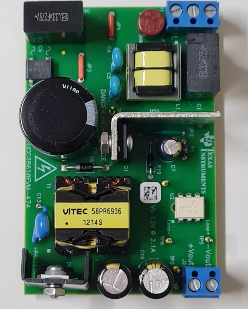
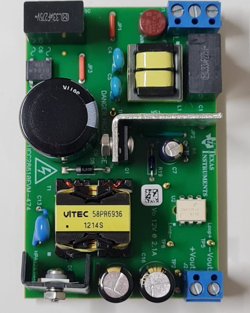
Now, let’s move on to designing a green mode SMPS. For this example, we’ll design a 25W power supply using the UCC28610 IC, which is a green mode flyback controller from Texas Instruments (TI).
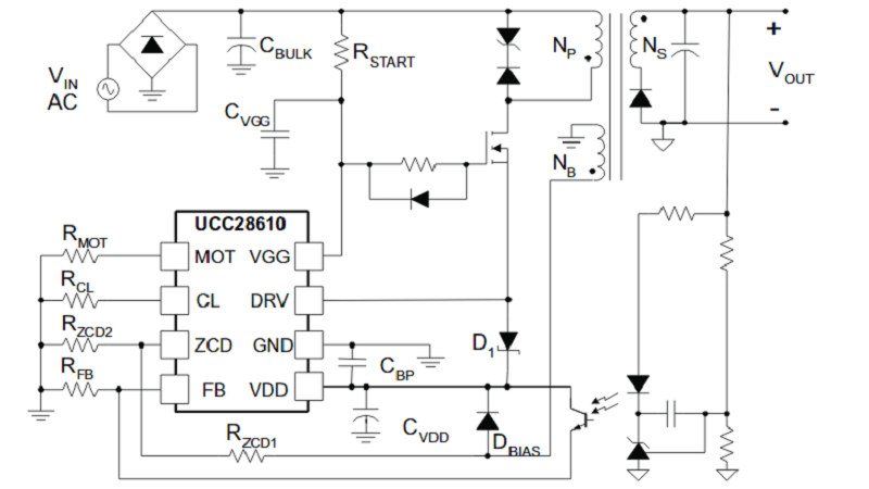
Key Features of the UCC28610 IC:

  • Low No-Load Power Consumption: The UCC28610 operates with low power consumption when there is no load, making it ideal for standby applications.
  • High Efficiency: The IC works in discontinuous conduction mode (DCM), reducing switching losses and improving efficiency at lighter loads.
  • Cascode Driver: The IC uses a cascode driver to drive the external MOSFET, which provides fast startup and lower input power under no-load conditions.
  • Current Mode Control: The feedback uses current mode control instead of voltage mode, reducing power consumption during no-load operation.

Design Steps:

  1. Determine the input and output specifications: Choose the input voltage range (e.g., 90V to 265V AC) and output voltage (e.g., 12V DC).
  2. Select the Transformer: Choose a transformer with an appropriate turn ratio to provide the desired output voltage.
  3. Choose the MOSFET: Select a high-voltage MOSFET that can handle the input voltage and switching frequency.
  4. Set Feedback and Control Circuit: Use the UCC28610’s feedback pin to regulate the output voltage by monitoring the current and adjusting the switching duty cycle.

By designing this power supply using the UCC28610 IC, we ensure low energy consumption during standby and high efficiency when the load is active.

You get guidance here to make a battery charger with cc cv function.Learn more here to make your charger: Understanding SMPS (Switched-Mode Power Supply): How it Works and How to Design It

Conclusion

SMPS is a versatile and efficient power supply solution used in a wide range of electronic devices. Among various topologies, the flyback converter is favored for its simplicity, cost-effectiveness, and ability to provide galvanic isolation. Designing a green mode SMPS using controllers like the UCC28610 ensures minimal energy waste during low-load or standby conditions, which is essential for energy-saving applications.

In future posts, we will delve deeper into the practical design steps, including schematic diagrams and component selection, for creating an efficient 25W green mode SMPS using the flyback converter topology.

Stay electrified and keep learning!


References:

  1. Texas Instruments: UCC28610 Green Mode Flyback Controller.
  2. SMPS Design and Topologies: Exploring different DC-DC converter topologies, including flyback and buck converters.
  3. Application of SMPS in Consumer Electronics: How SMPS are used in various consumer devices.

Note: You can find further design guides and application notes from Texas Instruments and other semiconductor manufacturers to assist in your SMPS design journey.

Loading

CC-CV DC-DC Converters: The Key to Efficient Battery Charging

CC-CV DC-DC Converters

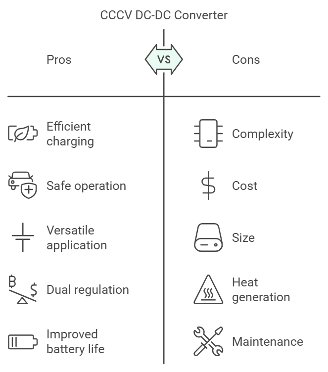
Hey everyone, today we’re exploring a vital component in battery charging systems—the DC-DC converter with constant current-constant voltage (CCCV) regulation. This versatile technology can regulate both current and voltage, making it perfect for efficient and safe battery charging. Let’s dive into how this converter works, its applications, and why it’s essential for charging various types of batteries.

napkin-selection-2

What is a CCCV DC-DC Converter?

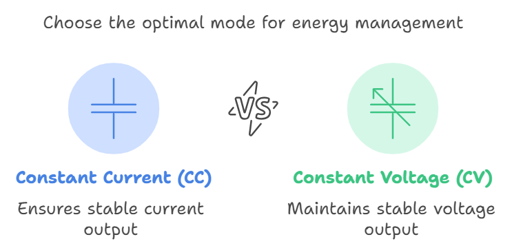
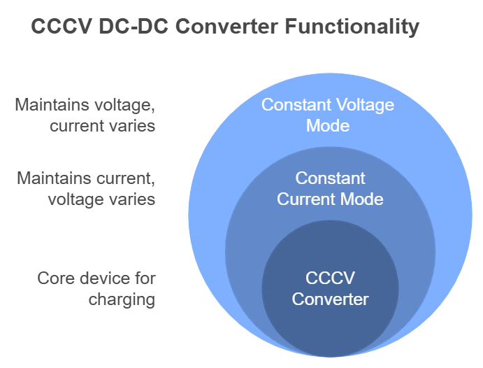
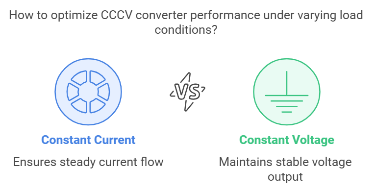
A CCCV DC-DC converter is a device that provides either constant current (CC) or constant voltage (CV) depending on the needs of the connected load. According to Ohm’s law, for any given resistive load, we can control only one of the two—current or voltage—while the other varies. This unique property makes CCCV converters highly adaptable, enabling them to operate either in constant current mode (where voltage changes) or constant voltage mode (where current varies with load).

napkin-selection-5

Applications of CCCV Converters

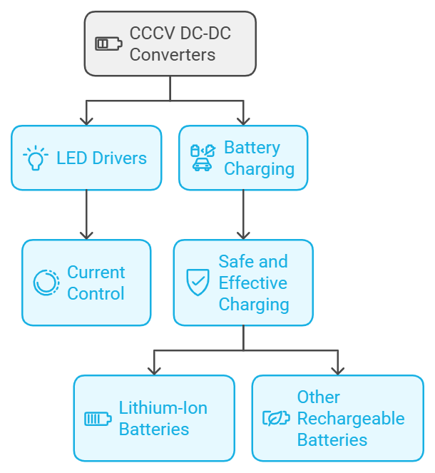
CCCV DC-DC converters have a range of applications:

  • LED Drivers: LEDs require specific current control to avoid burnout.
  • Battery Charging: Charging batteries or supercapacitors safely and effectively is a primary use case, especially for lithium-ion and other rechargeable batteries that need a CCCV configuration.
CC-CV DC-DC Converters

CCCV Charging: A Hybrid Approach

Battery charging with CCCV converters uses a hybrid method to control both current and voltage. The charging process typically begins with constant current mode and then transitions to constant voltage mode once the battery reaches a certain threshold. Here’s how it works:

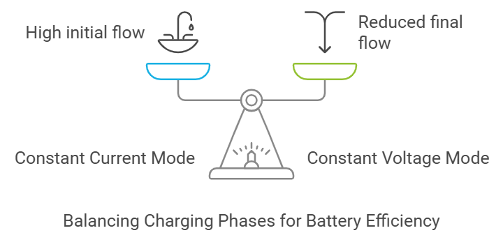
  1. Constant Current (CC) Mode: The battery charges at a constant current, maximizing the initial charge rate.
  2. Constant Voltage (CV) Mode: When the battery’s voltage reaches the target threshold, the converter switches to constant voltage mode, which slowly tapers off the current until the battery is fully charged.

This two-stage charging process is ideal for lithium-ion batteries, used in everything from electric vehicles to portable electronics, ensuring fast and safe charging.

A Simple Analogy: CCCV Charging Explained

Let’s compare this process to filling a paper coffee cup from a large water reservoir. If you open the tap fully, the cup might tear from the high pressure. Instead, you start with a controlled flow of water, which is similar to charging a battery in constant current mode. As the cup nears its full capacity, you reduce the flow (like switching to constant voltage mode) until it’s completely full. Here, the cup represents the battery, the water flow represents the charging current, and the person adjusting the tap represents the charge controller.

CC-CV DC-DC Converters

How CCCV Charging Works in Detail

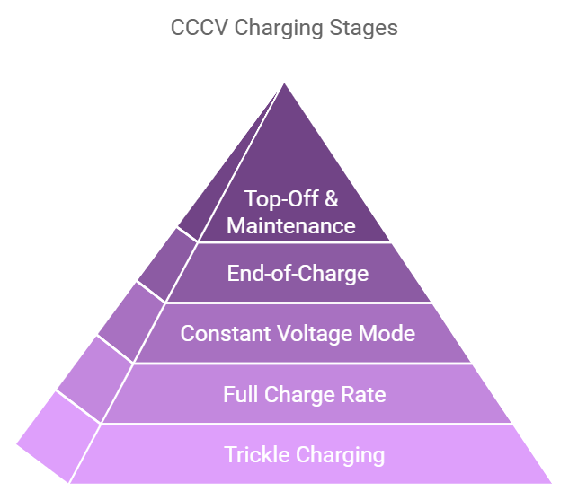
  1. Trickle Charging: When the charger detects a deeply discharged battery (with voltage below a certain level), it begins with a gentle trickle charge at around 10% of the full rate. This phase protects the battery from high currents that could cause internal damage.
  2. Full Charge Rate: Once the battery reaches a safe pre-charge voltage, the charger shifts to constant current mode, charging at a faster rate. This is where the bulk of charging happens, rapidly bringing the battery up to 70-80% capacity.
  3. Constant Voltage Mode: When the battery reaches a higher voltage threshold, the charger switches to constant voltage mode. Here, the voltage is held steady while the current decreases gradually as the battery approaches full charge.
  4. End-of-Charge: When the charging current drops to about 10% of the original rate, the charger considers the battery fully charged. In this stage, the charger might turn off or switch to maintenance mode.
  5. Top-Off and Maintenance: If the battery voltage later drops below a recharge threshold (for instance, due to self-discharge or connected loads), the charger will begin the cycle again, keeping the battery at optimal levels.
CC-CV DC-DC Converters: The Key to Efficient Battery Charging

Why CCCV Charging is Essential

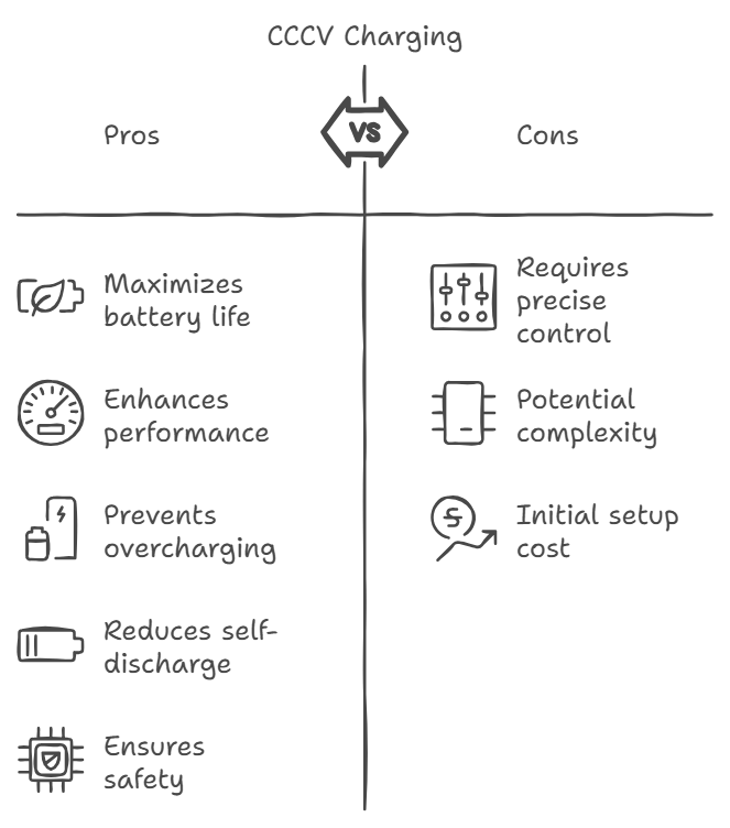
This charging method not only maximizes battery life and performance but also prevents overcharging and self-discharge, common issues in battery maintenance. For lithium-ion batteries, which are particularly sensitive to voltage fluctuations, CCCV charging ensures safety and efficiency.

CC-CV DC-DC Converters: The Key to Efficient Battery Charging

What’s Next?

In our upcoming posts, we’ll explore the control mechanisms in CCCV converters and simulate different load conditions to illustrate constant current and constant voltage modes in action. Stay tuned to understand the intricacies of load variations and to see this technology in real-time simulations.

CC-CV DC-DC Converters

Digital Electronics: A Comprehensive Guide

video-thumbnail-understanding-logic-gates

Introduction to Digital Electronics

Digital electronics is a branch of electronics that focuses on circuits and devices that operate using digital signals. Unlike analog electronics, which deals with continuous signals, digital electronics uses discrete values—typically binary 0s and 1s. These binary signals allow for the creation of systems that are more reliable, easier to design, and more immune to noise, which is why digital electronics is a cornerstone of modern technology.

From computers and smartphones to embedded systems and digital communication, digital electronics plays a key role in almost every electronic device you interact with today. In this article, we will explore the core concepts, components, and applications of digital electronics, providing an in-depth look at how it has transformed the technological landscape.


Chapter 1: Basic Concepts in Digital Electronics

1.1 Analog vs. Digital Signals

Before delving into the details of digital electronics, it’s essential to understand the difference between analog and digital signals.

  • Analog Signals: Continuous in nature, these signals can take on any value within a range. They are commonly used in audio, radio, and other communication systems.
  • Digital Signals: In contrast, digital signals have discrete values, typically represented by binary numbers (0 and 1). These signals are more robust in terms of noise immunity, making them ideal for modern electronic systems.

1.2 Binary Number System

Digital electronics is based on the binary number system, which uses only two digits: 0 and 1. Each binary digit (or bit) represents a power of 2. Binary numbers are used because digital systems operate using two voltage levels—high (1) and low (0). These two states are easy to distinguish electrically, leading to more reliable operations.

For example, the binary number 1011 represents:

  • ( 1 \times 2^3 = 8 )
  • ( 0 \times 2^2 = 0 )
  • ( 1 \times 2^1 = 2 )
  • ( 1 \times 2^0 = 1 )

Thus, 1011 in binary is equivalent to 11 in decimal.

1.3 Logic Gates

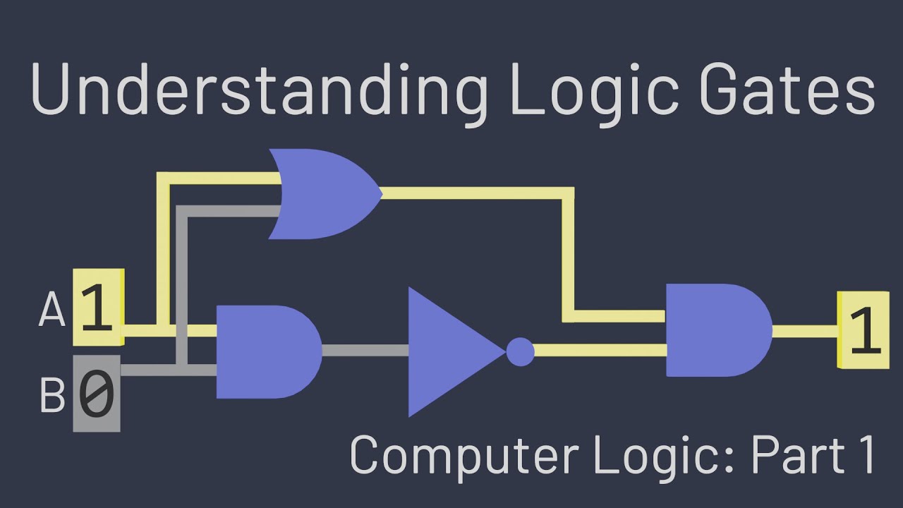
Logic gates are the fundamental building blocks of digital circuits. They perform basic operations on binary numbers, such as addition, multiplication, and comparison. The common types of logic gates are:

  • AND Gate: Outputs 1 only when both inputs are 1.
  • OR Gate: Outputs 1 when at least one input is 1.
  • NOT Gate: Inverts the input—if the input is 1, the output is 0, and vice versa.
  • NAND Gate: Outputs the opposite of an AND gate; it outputs 0 only when both inputs are 1.
  • NOR Gate: Outputs the opposite of an OR gate; it outputs 1 only when both inputs are 0.
  • XOR Gate (Exclusive OR): Outputs 1 when the inputs are different.
  • XNOR Gate (Exclusive NOR): Outputs 1 when the inputs are the same.

These gates can be combined to perform complex operations, forming the basis of all digital circuits.

1.4 Truth Tables

A truth table lists all possible input combinations for a logic gate and the corresponding output. For instance, a truth table for the AND gate looks like this:

ABA AND B
000
010
100
111

Truth tables are essential tools for understanding and designing digital circuits.


Chapter 2: Digital Components

2.1 Flip-Flops

Flip-flops are basic memory elements used in digital circuits to store one bit of data. They are the foundation of more complex memory and storage devices. The common types include:

  • SR Flip-Flop: Stores 1 when “Set” is high and 0 when “Reset” is high.
  • D Flip-Flop: Data is transferred to the output on the rising or falling edge of a clock signal.
  • JK Flip-Flop: A more versatile version of the SR flip-flop that solves the problem of indeterminate states.
  • T Flip-Flop: Toggles its state on each clock cycle.

2.2 Multiplexers and Demultiplexers

  • Multiplexers (MUX): Devices that select one of many inputs and direct it to a single output. This is controlled by select lines, which determine which input is connected to the output.
  • Demultiplexers (DEMUX): Devices that take a single input and distribute it to one of many outputs, again controlled by select lines.

2.3 Counters

Counters are sequential circuits that count pulses or clock signals. They can be classified into:

  • Asynchronous Counters (Ripple Counters): Count without a synchronized clock signal, leading to a slower response.
  • Synchronous Counters: Use a common clock signal, ensuring that all bits are updated simultaneously, allowing for faster operation.

2.4 Registers

Registers are a type of memory circuit used to store multiple bits of data. Data in a register can be shifted (shift registers) or stored in parallel (parallel registers), making them essential in applications like microprocessors and digital signal processing (DSP).


Chapter 3: Boolean Algebra and Karnaugh Maps

3.1 Boolean Algebra

Boolean algebra is a branch of mathematics that deals with binary variables and logic operations. It helps in simplifying logic expressions and designing digital circuits more efficiently. The basic operations in Boolean algebra are:

  • AND: Represented by multiplication or a dot (e.g., ( A \cdot B )).
  • OR: Represented by addition or a plus sign (e.g., ( A + B )).
  • NOT: Represented by a bar or prime (e.g., ( \overline{A} ) or ( A’ )).

3.2 Laws of Boolean Algebra

Some important laws include:

  • Identity Law: ( A + 0 = A ), ( A \cdot 1 = A )
  • Null Law: ( A + 1 = 1 ), ( A \cdot 0 = 0 )
  • Complement Law: ( A + \overline{A} = 1 ), ( A \cdot \overline{A} = 0 )
  • Distributive Law: ( A \cdot (B + C) = A \cdot B + A \cdot C )

3.3 Karnaugh Maps (K-Maps)

K-maps are a visual method of simplifying Boolean expressions. By organizing the truth table into a 2D grid, adjacent cells that share common factors can be grouped, leading to simplified expressions.

For example, a 2-variable K-map would look like:

AB00011110

K-maps allow for quick and efficient simplification of logic functions, especially when dealing with multiple variables.


Chapter 4: Combinational Circuits

4.1 Adders

  • Half Adder: Adds two single bits, producing a sum and a carry.
  • Full Adder: Adds three bits (two inputs and a carry from the previous stage) and produces a sum and carry output.

Multiple full adders can be connected to create multi-bit adders used in arithmetic circuits like ALUs (Arithmetic Logic Units).

4.2 Subtractors

  • Half Subtractor: Performs binary subtraction on two single bits, producing a difference and a borrow.
  • Full Subtractor: Extends the half subtractor by allowing the subtraction of three bits (including a borrow from the previous stage).

4.3 Encoders and Decoders

  • Encoders: Convert information from one format or code to another, typically reducing the number of bits needed to represent a piece of data.
  • Decoders: Perform the reverse operation of encoders, converting encoded data back into its original form. These are essential in communication systems, where encoded data must be decoded for interpretation.

4.4 Comparators

Comparators are circuits that compare two binary numbers and determine whether one is greater than, less than, or equal to the other. They are useful in applications like sorting, error detection, and decision-making.


Chapter 5: Sequential Circuits

5.1 Clocked Sequential Circuits

Sequential circuits have outputs that depend not only on current inputs but also on past inputs (due to memory elements like flip-flops). The clock signal synchronizes changes in the state of these circuits, ensuring orderly operation.

5.2 Finite State Machines (FSM)

FSMs are used to model systems that can be in one of several distinct states. Transitions between states are triggered by inputs or events. FSMs can be:

  • Mealy Machines: Outputs depend on both the current state and inputs.
  • Moore Machines: Outputs depend only on the current state.

5.3 Shift Registers

Shift registers are used to store data and move it in a specific direction (left or right) based on a clock signal. These are essential in applications like data serialization, parallel-to-serial conversion, and digital signal processing.


Chapter 6: Memory in Digital Electronics

6.1 ROM (Read-Only Memory)

ROM is a type of memory that can only be read from; it cannot be modified (except during manufacturing or programming

). It stores data permanently and is often used for storing firmware or other essential data in systems.

6.2 RAM (Random Access Memory)

RAM is volatile memory, meaning it loses its data when power is turned off. It is used for temporary data storage in computers and other digital devices. Types of RAM include:

  • SRAM (Static RAM): Stores data in flip-flops and retains data as long as power is supplied.
  • DRAM (Dynamic RAM): Stores data in capacitors and needs to be refreshed periodically to maintain the data.

6.3 EEPROM (Electrically Erasable Programmable Read-Only Memory)

EEPROM can be electrically erased and reprogrammed, making it useful for storing data that needs to be retained when the power is off but can be modified, such as in microcontroller applications.


Chapter 7: Digital Communication

7.1 Digital Modulation Techniques

Digital communication systems rely on various modulation techniques to encode digital data onto analog signals for transmission. Common techniques include:

  • Amplitude Shift Keying (ASK): Varies the amplitude of the carrier signal based on the digital data.
  • Frequency Shift Keying (FSK): Varies the frequency of the carrier signal.
  • Phase Shift Keying (PSK): Varies the phase of the carrier signal.

7.2 Error Detection and Correction

Digital communication systems often use error detection and correction techniques to ensure data integrity. Common methods include:

  • Parity Bit: Adds an extra bit to data to detect single-bit errors.
  • Checksums and CRC (Cyclic Redundancy Check): Used to detect more complex errors in data transmission.
  • Hamming Code: A forward error correction method that allows both error detection and correction.

Chapter 8: Applications of Digital Electronics

Digital electronics finds applications in numerous fields, including:

  • Computers and Microprocessors: The entire computing industry is built on digital electronics, from simple logic circuits to complex processors.
  • Communication Systems: Digital electronics is at the core of modern telecommunication systems, allowing efficient transmission of data over long distances.
  • Embedded Systems: Digital circuits enable the creation of specialized devices for automotive, industrial, and consumer electronics.
  • Control Systems: Digital electronics are used in feedback systems, automation, and robotics for precision control.
  • Signal Processing: Digital signal processing (DSP) uses digital circuits to process and analyze real-world signals, such as audio, video, and sensor data.

Conclusion

Digital electronics is the foundation of modern technology, enabling the development of computers, communication devices, and automated systems. With its emphasis on binary signals, logic gates, memory elements, and sequential circuits, digital electronics has revolutionized how we store, process, and transmit information. Understanding the principles of digital electronics opens up a wide range of possibilities, from designing simple circuits to developing complex microprocessors and embedded systems.

Whether you’re a student, hobbyist, or engineer, mastering digital electronics is essential in today’s tech-driven world. The continued evolution of digital electronics promises even more exciting innovations in the future, shaping the way we interact with technology.

12 volt electric fuel pump

video-thumbnail-fuel-transfer-pumps-12-24v-dc-40-70lpm

Here’s a more detailed explanation of 12-volt electric fuel pumps:

Components and Operation:

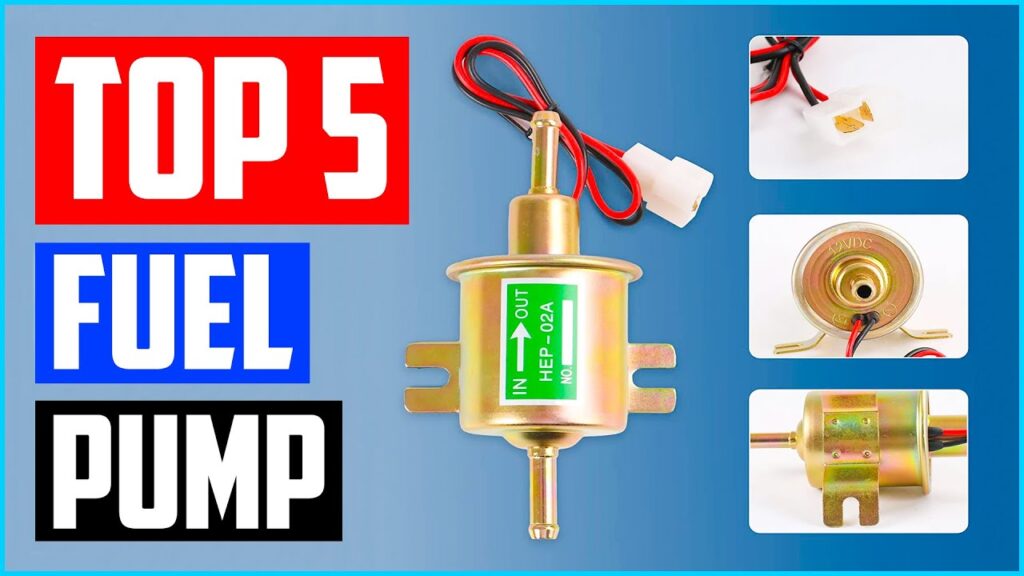
A typical 12-volt electric fuel pump consists of:

  1. Motor: Converts electrical energy into mechanical energy.
  2. Impeller: Creates suction and pressure to move fuel.
  3. Pump Housing: Contains the impeller and motor.
  4. Inlet and Outlet Ports: Connect to fuel lines.
  5. Filter: Protects the pump from debris.
  6. Pressure Regulator: Maintains optimal fuel pressure.
video-thumbnail-top-5-best-electric-fuel-pump-in-2022-review-2

How it Works:

  1. The motor spins the impeller, creating suction.
  2. Fuel is drawn into the pump through the inlet port.
  3. The impeller pushes fuel out through the outlet port.
  4. The pressure regulator ensures optimal fuel pressure.

Types of 12-Volt Electric Fuel Pumps:

  1. In-Tank Pumps: Located inside the fuel tank, these pumps are:
    • Compact
    • Quiet
    • Less prone to contamination
  2. External Pumps: Mounted outside the fuel tank, these pumps are:
    • Easier to install and maintain
    • More versatile
    • Suitable for high-performance applications
  3. High-Pressure Pumps: Designed for high-performance engines, these pumps deliver:
    • Higher fuel pressure (up to 60 psi)
    • Increased flow rates
  4. Low-Pressure Pumps: Suitable for smaller engines or low-flow applications:
    • Lower fuel pressure (around 3-10 psi)
    • Reduced flow rates

Specifications and Ratings:

When selecting a 12-volt electric fuel pump, consider:

  1. Flow Rate: Measured in gallons per hour (GPH) or liters per hour (LPH).
  2. Fuel Pressure: Measured in pounds per square inch (psi).
  3. Power Consumption: Measured in amps (A).
  4. Voltage: 12 volts DC.
  5. Operating Temperature: Range of temperatures the pump can operate within.

Installation Considerations:

  1. Wiring: Ensure proper wiring and electrical connections.
  2. Fuel Line Sizing: Choose fuel lines that match the pump’s flow rate.
  3. Pump Mounting: Secure the pump to prevent vibration and damage.
  4. Fuel Filter: Install a fuel filter to protect the pump from debris.
  5. Pressure Regulation: Ensure proper pressure regulation.

Troubleshooting Tips:

  1. No Fuel Pressure: Check power supply, wiring, and pump operation.
  2. Low Fuel Pressure: Inspect fuel filter, fuel lines, and pump mounting.
  3. High Fuel Pressure: Check pressure regulator and fuel line sizing.
  4. Pump Noise: Verify proper pump mounting and fuel line routing.

Popular Brands and Models:

Some well-known brands and models include:

  1. AEM 50-1000
  2. Aeromotive 340 Stealth
  3. Bosch 0 580 254 043
  4. Carter Fuel Systems P5001
  5. Delphi FE2014
  6. Edelbrock 17920
  7. Holley 12-453
  8. MSD 2923

Applications:

12-volt electric fuel pumps are used in:

  1. Automotive (cars, trucks, SUVs)
  2. Marine (boats, watercraft)
  3. Industrial (generators, pumps)
  4. Agricultural (tractors, farm equipment)

Do you have specific questions, or would you like more information on a particular aspect of 12-volt electric fuel pumps?