
A sine wave inverter converts DC (Direct Current) power into AC (Alternating Current) power. It is commonly used in applications such as solar power systems, UPS (Uninterruptible Power Supply) systems, and portable power systems for camping or outdoor use.
The DSPIC30F2010 microcontroller is widely recognized for its exceptional performance and affordability, making it a popular choice for implementing sine wave inverters. In this article, we will explore the design and implementation of a sine wave inverter using the DSPIC30F2010 microcontroller.
Design Considerations:
Before embarking on the design of the circuit and code for the sine wave inverter, it is important to take into account several design considerations. Here are some examples:
The size of the components used in the circuit will be determined by the resulting power of the inverter. The power output can vary from a few watts to several kilowatts, depending on the specific application.
The voltage output of the inverter will depend on the specific application. As an electrical engineer, you may encounter different voltage outputs in a solar power system, such as 120V AC or 240V AC.
The outcome recurrence of the inverter will depend on the application. As an electrical engineer, it’s worth noting that the standard frequency in the US is 60Hz, whereas in Europe it’s 50Hz.
Efficiency is a crucial factor to consider when evaluating the inverter’s impact on the overall performance and cost of the system. An inverter with improved efficiency will result in reduced power consumption and lower output intensity.
The waveform of the resulting signal is an important consideration. A pure sine wave output is the preferred waveform as it produces minimal harmonic distortion and poses less risk of damaging delicate devices.
Designing Circuits:
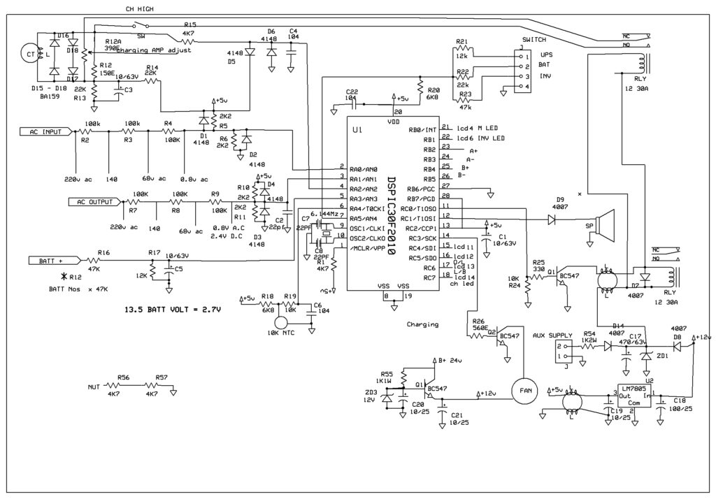
The circuit design for the sine wave inverter using the DSPIC30F2010 microcontroller is shown in the figure below.
Graph of a Sine Wave Inverter Circuit
The circuit consists of several components:
DC Power Supply: The DC power supply can be a battery or a solar board depending on the application.
The DSPIC30F2010 microcontroller serves as the central component of the inverter. It generates a PWM signal that is used to power the MOSFETs.
The IR2110 MOSFET driver is used to drive the MOSFETs. It produces a high voltage and high current output that is intended to power the MOSFETs.
Utilizing MOSFETs, the DC power supply can be switched on and off at the frequency of the PWM signal. The circuit can use IRF3205 MOSFETs or similar options.
LC Channel: The LC channel consists of an inductor and capacitor that work together to optimize the square wave output of the MOSFETs, resulting in a sine wave output.
Load: The heap is linked to the outcome of the LC channel. The heap can serve as a resistive load or an AC motor depending on the application.
Hey there, I’m hosting a giveaway for an awesome inverter project! This project is a digital pure sine wave inverter based on the dspic30f2010 microcontroller. It has some really cool functions that you’ll love!
- Presetting low battery levels through calibration
- Safeguarding against 440v mains
3. The current range of the PWM battery charger is from 5A to 20A.
- Protection against inverter overload
- Protection against short circuits
- Sensitive to current and voltage in isolated AC mains.
- The voltage range is from 100V AC to 230V AC at 50/60 hertz, with low noise.
LCD display is used to show various important information such as battery voltage, output voltage, input voltage, load wattage, charging current, and more. In this case, you have the option of choosing between a 7.162 or 164 LCD display.
Video Of the inverter project info
>>You can download the full project file here <<
dspic30f2010 sine wave inverter source code
dspic30f2010 inverter hex file
please comment below.
follow our youtube channel here to get notified when there is a new update.
bsingh32
Hello Brother,
I need the solar invertor project with complete details Hex file gerber file for pcb and component details for school project