Solar energy is a highly sustainable source of energy available today. With the increasing affordability and efficiency of solar panels, they are gaining popularity for both residential and commercial use. To maximize the energy output of a solar panel, it is crucial to use a solar controller that can track the maximum power point (MPP) of the panel. An excellent choice for a solar controller project is the DSPIC30F2010 microcontroller. It is highly suitable for implementing an MPPT (Maximum Power Point Tracking) algorithm.
The DSPIC30F2010 is a powerful 16-bit microcontroller from Computer Chip Innovation that offers a wide range of features, including an integrated ADC, PWM outputs, and a high-performance CPU. These elements aim to make the best decision for performing an MPPT calculation for a solar controller project. With the coordinated ADC, you can measure the voltage and current of the solar panel, and then use the PWM results to adjust the duty cycle of a DC converter. With the elite presentation CPU, the MPPT calculation is handled in real-time, ensuring that the solar panel always operates at its highest power point.
When setting up an MPPT solar controller with the DSPIC30F2010, the first thing you need to do is select an appropriate DC converter. The DC converter is responsible for stepping down the high-voltage DC output of the solar panel to a lower voltage that can be used to power the load. The choice of the DC converter will depend on the voltage range and power rating of the solar panel. There are several common types of DC converters that can be used, such as buck-boost, SEPIC, and Cuk converters.
Next, we need to perform an MPPT calculation to track the maximum power point (MPP) of the solar panel. Several MPPT calculations are available, but the most common ones include Irritate and Notice (P&O), Steady Conductance, and Fragmentary Open Circuit Voltage. These calculations involve continuously adjusting the duty cycle of the DC converter to track the maximum power point (MPP) of the solar panel. The DSPIC30F2010 has the capability to perform continuous calculations.

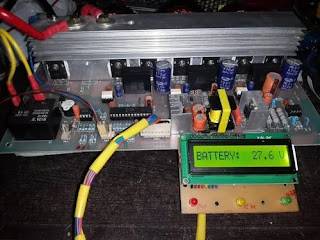
Additionally, the DSPIC30F2010 can be used to implement a user interface for monitoring and controlling the solar controller. It should be possible by using an LCD display, buttons, or a sequential point of interaction such as UART or SPI. The UI can be used to display the current power output of the solar panel, the battery voltage, and other relevant information. The client can also utilize the connection point to adjust the MPPT calculation parameters, such as the step size and the assembly measures.
One advantage of using the DSPIC30F2010 for an MPPT solar controller project is its ability to handle various obstacles and perform real-time calculations. The microcontroller is capable of handling obstacles from the ADC, the PWM outputs, and the UI, all while performing the MPPT algorithm calculations. Ensuring that the solar panel operates at its peak power point, even in varying environmental conditions.
In summary, the DSPIC30F2010 is a highly suitable microcontroller for implementing an MPPT solar controller project. With its incorporated ADC, PWM results, and superior execution CPU, this device is an excellent choice for performing an MPPT calculation, controlling the DC converter, and providing a user interface for monitoring and controlling the solar controller. By utilizing its advanced handling capabilities, the DSPIC30F2010 ensures that the solar board operates at its peak power point, resulting in optimal energy output and efficiency.
Features of this Dspic30f2010 Mppt
1. Achieving a remarkable working efficiency of 90%
2. Input voltage can reach up to 250V PV voltage.
3. The charging current can reach up to 70A, providing a high level of power.
4. The MPPT controller effortlessly detects the batteries. It is compatible with a wide range of battery systems, including 12V, 24V, 36V, 48V, 72V, 96V, 120V, and 144V.
IGBT Driver circuits commonly utilize the TLP250 as an Isolator driver for IGBTs.

6. Implementing an IGBT protection circuit to safeguard the IGBTs in the event of a fault.
7. Over-current protection is an important aspect to consider.
8. Protection against surges in solar or PV systems
There are three stages of charging control.
10. It can replace alternative MPPT controller boards.
11. Protection against high temperatures;
12. Concerning PV voltage protection
13. Change topology that is interleaved
14. Programming the hex file into the dspic30f2010 does not require any programming skills.
Take note of the inductor values.
Either 68uh or 73uh will work. The AWG 0.8mm (or gauge 20) copper wire can handle up to 5 Amps, meaning that the more wires used, the higher the current in each of the inductors.
yeasin
tell me the size of the pcb?plz?& trun of sofer coill….