
A simple electronic circuit known as the Joule Thief circuit can be used to raise the voltage of a low-voltage source, such as a single AA battery or solar cell. It was initially introduced by Z. Kaparnik in 1999, and its name refers to the way it could “take” energy from an almost empty battery to keep a circuit running.
The voltage from the input source is advanced by a transformer in the circuit, which then swiftly turns on and off the current via a transistor. This causes energy to be stored in the attractive field of the transformer and to be delivered as a higher voltage upon the transistor’s shutdown. This creates a feedback loop that permits the circuit to continue operating even in situations where the input voltage is less than the anticipated output value.
A transistor, a ferrite center transformer, a diode, a capacitor, and a few resistors are some of the necessary parts needed to build a Joule Thief circuit that can sustain a 1.2V source up to 3V. The steps of building the circuit are as follows:
Turn the transformer on first. One way to wind wire around a small ferrite center, such as one from an old radio, is to wind ten turns around it. This breeze will be crucial.
Next, wind a total of thirty to forty turns of wire around the necessary winding. This breeze will be optional.
Connect the transistor’s gatherer to the board after patching it together and making sure the transformer is twisted correctly.
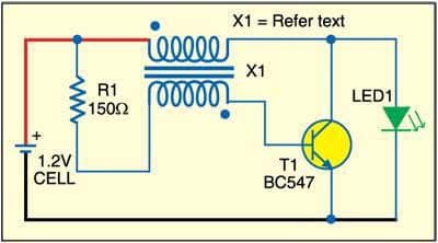
Connect the capacitor’s positive lead to the positive lead of the 1.2V source, and connect the capacitor’s negative lead to the transistor’s producer.
Connect the diode’s anode to the transformer’s auxiliary twisting, and connect the diode’s cathode to the output’s positive lead.
To stabilize the circuit and limit the current, put a resistor at the end. It is possible to connect a 10k resistor between the transistor’s base and emitter and a 1k resistor between the transistor’s base and the positive lead of the 1.2V source.
Once the circuit is assembled, you may test it by connecting the output leads of a voltmeter to it. The voltmeter should read a voltage of about 3V when the circuit is turned on. Another way to test the circuit is to connect a load, such as a drive, to the output and observe if it illuminates.
Advantages:
efficiency: The Joule Thief circuit is an effective way to power small electronic devices because it is made to extract the most amount of energy from a low-voltage source.
2. Low Voltage Activity: The circuit can occasionally operate at very low voltages of as little as 0.3V, which makes it helpful in situations where conventional circuits would not function.
3. Practical: The Joule Thief circuit is an economical solution for powering small electronic devices since it can be operated with a few affordable components.
4. Compact size: The circuit is tiny and easily integrated into smaller electronic devices when room is at a premium.
Disadvantage:
Voltage is unstable: Depending on the input voltage, load current, and component robustness, the circuit’s output voltage may fluctuate.
2. Limited power output: With only a few milliwatts of power, the Joule Thief circuit isn’t suitable for applications requiring large power output.
3. Complexity: Designing and researching the circuit might be challenging, particularly for amateurs who are interested in electrical standards.
4. Noise and impedance: The circuit’s switching activity may produce noise and electromagnetic interference that may affect nearby electrical devices.
All things considered, the Joule Thief circuit is a practical and effective circuit that supports low-voltage sources to power tiny electrical devices. However, some drawbacks and obstacles need to be taken into account when building and operating the circuit.
All things considered, the Joule Thief circuit is a practical and adaptable circuit that may be used for several purposes, such as charging solar-cell batteries and powering tiny electronic devices. You can create custom Joule Thief circuits to meet your specific needs by comprehending the basic principles of the circuit’s operation and construction.