
This project that I am presenting today involves an IR2153 push-pull inverter. The circuit is designed to convert a 12VDC voltage from a battery into a 220V AC voltage. The circuit utilizes the IR2153 IC as the oscillator and MOSFETs to drive the transformer, resulting in a push-pull configuration that enables efficient voltage conversion. Here are the steps to construct an IR2153 push-pull inverter using MOSFETs.
Components needed:
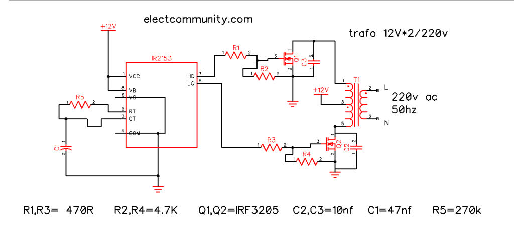
– IR2153 integrated circuit
– High-quality PCB BoaRequired components:
The IR2153 integrated circuit
– Utilizing MOSFETs IRF3205
– Transformer (12V-0-12V to 220V)
– Capacitors (47nF, 10nF)
– Resistors (470Ω, 270kΩ, 4.7kkΩ)
– Perf PCB Board
Here are the steps:
Begin by placing the components on the PCB board, starting with the IR2153 integrated circuit and MOSFETs.
If you want to stabilize the circuit, you can connect a 2200uF capacitor to the positive DC source and the positive terminal of the transformer.
Attach a 47nF capacitor to pin 3 and ground, and place a 10nF capacitor in parallel with the drain and source pins of each MOSFET.
Attach the 270kΩ resistor to pins 2 and 3 of the IR2153 IC
Attach the 470Ω resistor to the MOSFET gate driver.
Connect one of the MOSFET’s drain pin to one side of the transformer and the second MOSFET’s drain to the other side of the transformer.
Ensure that the sources of the MOSFETs are properly connected to the DC source.
Lastly, attach the heat sink to the MOSFETs for effective heat dissipation.
Test the inverter with a power load of up to 200 watts, just like an electrical engineer would do.
In conclusion:
A push-pull inverter utilizing MOSFETs, such as the IR2153, is an efficient and dependable option for converting DC voltage into high AC voltage. Ensure precise soldering of the MOSFETs, utilizing the appropriate component rating and adhering to their polarity. Exercise caution when handling the circuit, as it involves a high-voltage project.
The push-pull configuration of the MOSFETs enhances the efficiency of the inverter, with two sides effectively managing the load. Using a heat sink to prevent the MOSFET from overheating is important. Follow the steps I demonstrated earlier to create the IR2153 push-pull inverter. To enhance power and efficiency, consider increasing the number of MOSFETs. Additionally, ensure that you select an appropriate transformer for your power requirements.
Please consider following our social media page to stay updated at all times.
Finally, connect the heat sink to the MOSFETs to ensure proper heat dissipation.