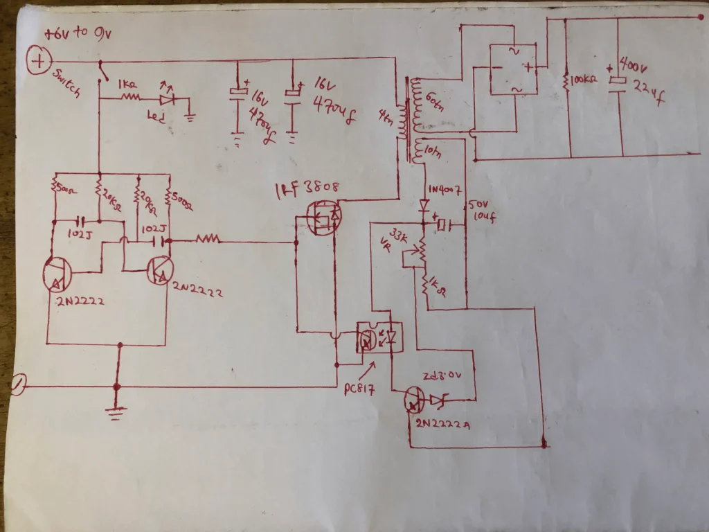
This project involves a basic boost converter that increases a 6V DC voltage to high-frequency AC. The AC is then converted using a full bridge rectifying diode setup with a capacitor at the output. What’s interesting about this project is that it doesn’t rely on any integrated circuits. Instead, the oscillator circuit is constructed using a two-transistor astable multivibrator circuit, with a frequency of 20kHz. Additionally, you have the flexibility to adjust the output voltage to your desired level, ranging from 5V to 100V DC, depending on your specific needs and application.
Here are the necessary components for this project:
MOSFET IRF3808.
All transistors are 2n2222a.
Using a PC817 optocoupler for feedback sensing
33k variable resistor
There are three capacitors with a capacitance of
102J, two capacitors with a voltage rating of
16V and capacitance of 470uF,
capacitor with a voltage rating of 400V and capacitance of 22uF
capacitor with a voltage rating of 50V and capacitance of 10uF.
Here are the diodes
bridge rectifier with a current rating of 2 amps
Zener diode with a voltage rating of 3.0 volts.
One LED indicator
Perf board for electronic prototyping
Transformer winding info
Primary turns: 4tns. Secondary turns: 60tns. Feedback wind turns 10 turns.
Here are the resistors you need:
100k 1pc
20k 2pcs
500R 2pcs
100R 1pc
1k 2pcs
Note:
Using a thick heat sink is essential to ensure that the MOSFET does not overheat.
Key Factors to Keep in Mind:
To increase the efficiency of the circuit,
it is important to select appropriate component values, minimize losses in the inductor and diode, and ensure effective thermal protection for the MOSFET.
Switching converters
have the potential to generate electromagnetic interference (EMI) and radio frequency interference (RFI). For minimizing EMI/RFI, it is crucial to employ appropriate filtering components and layout techniques.
Note
It is important to note that switching converters have the potential to generate high voltages and currents, which can pose a safety risk. Ensure that proper safety measures are adhered to during the construction and testing of the circuit.
Conclusion
Building a DIY SMPS boost converter without an IC can be quite challenging, but with careful planning and assembly, it is definitely achievable. It is crucial to select suitable components, meticulously adhere to the schematic and assembly instructions, and conduct thorough testing of the circuit to guarantee dependable performance.